1987 MK 1 Catalina 34 Macerator Change
By Jon Windt; Della Jean
NOTE - Before doing any projects, I highly recommend that you first go through the “Critical Upgrades” list and verify that your boat has all of the applicable items addressed. There is a link on the Message Board (copied here) entitled “CRITICAL UPGRADES – DO THESE OR ELSE!!!” that will take you to them. It is a good way to both learn your boat and make sure it is safe. Don’t put it off.
Contents
Original Sanitation System Description
I purchased my Catalina 34 in April 2015. She is a 1987 MK1, hull #493.
The sanitation system starts with a ¾” hose connecting a dedicated thru hull under the head sink to the inlet of the Jabsco manual toilet. From there it travels through an anti siphon loop to the toilet bowl inlet. The discharge from the toilet is through a 1 ½” sanitation hose that connects to the upper outboard corner of the holding tank. There are three additional sanitation hoses connected to the holding tank. One is a 1” sanitation hose that connects the top of the holding tank to the vented station on deck. The second is a 1 ½” sanitation hose that connects the holding tank to the pump out fitting on the deck. The third is a 1 ½” sanitation hose that connects the lowest corner of the holding tank to a 90 degree elbow FPT x hose barb threaded onto the macerator pump. The macerator discharge is a 1” sanitation hose that connects to an anti siphon loop and ends at the thru hull.
The macerator pump is a Jabsco 18590-2092 marine run-dry macerator pump.
Background
When I bought my boat, I was told the previous owner had replaced all of the sanitation hoses and the macerator pump. So working on the macerator pump and sanitation system was not something I thought would need to be done for several years.
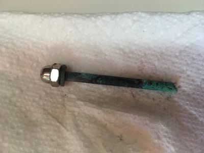
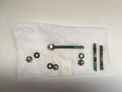
The PO may have done that, but I noticed the pump leaking while I was running the 12 volt outlet wires to a dedicated fuse block. Looking closer I noticed that an acorn nut was loose that holds the pump housing to the pump/motor. It turns out the nut wasn’t loose, the actual stud had broken. When I looked at the other three, a second stud had also failed. When I took the pump housing off it turned out all 4 were failing from severe corrosion.
This write up provides a summary of the macerator pump replacement I did with photos. I've numbered the photos to help with connecting the text to the associated photo.
This was not a very complicated project, but a very unpleasant one as you can imagine when dealing with the holding tank (and no shut off). All in all, I ran ~ 2 feet of new 1 1/2” ID SHIELDS RUBBER Poly X Sanitation Hose from the holding tank to the macerator pump. I also added ~3’ of new 1” ID SHIELDS RUBBER Poly X Sanitation Hose from the macerator pump discharge to the anti siphon valve. The motor is rated as 16A. The original 15A circuit breaker on the main distribution panel for the macerator pump/motor has plenty of margin to avoid nuisance trips, but decided to change it out to a 20A per the owners manual. The wiring is 10 AWG and had already been run as part of my complete electrical upgrade completed in the 1st Qtr of 2016. Electrical details for that are in a separate write-up entitled 1987 MK 1 Catalina 34 Electrical System Upgrade located in the "Electrical" section of the Tech WIKI.
As a final note, every boat is different. The routing, methods, and hose lengths I used may not work on your boat. Please read this only as a summary of what I did. This is one way, not the only way. Good luck and I hope you find this write up helpful.
Before Photos
The following photos show the boat before any work was done. The text description for each group of photos is above them. They are provided to help give you a picture of the starting point.
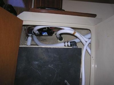
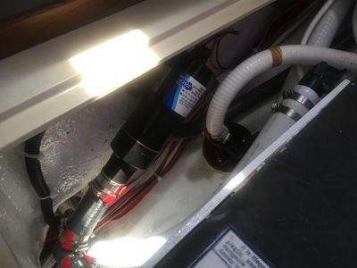
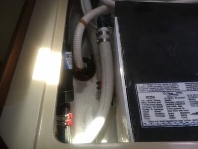
Photo (1) is the original macerator pump installation I had. The 1 ½” sanitation hose running under the macerator is the discharge hose from the toilet to the holding tank. The short 1 ½” sanitation hose connects the holding tank to the macerator pump via a Spears 90 degree 1 ½” FPT x 1 ½” hose barb threaded onto the macerator pump housing. The macerator discharge is a 1” hose connecting to the anti siphon loop located behind the seat cushion then to the thru hull. The 1” hose on the right side of the photo is the vent to the vented stantion on deck, and the other 1 ½” sanitation hose running to the right along the hull connects the holding tank to the pump out connection on deck.
FYI: This is an old photo. One of the first projects I did was to replace all thru hulls with proper flanged sea cocks and backing plates. Also removing the macerator pump for maintenance will be a horrible project so as part of fixing the leak I decided to change the layout to minimize future problems.
Photo (2) is a close up of one of the corroded studs that held the pump housing/pump/motor together. Photo (3) shows what is left of a couple of the original studs. This was the reason for the leak.
The Design Goals
- Fix the leaking macerator pump/motor with JABSCO Macerator Pump Service Kit (18598-1000).
- Replace the broken studs with JABSCO Macerator Stud Replacement Kits (17288-10000). These are SST bolts from Jabsco so this must not be an unusual problem.
- Replace the Spears 90 degree 1 ½” FPT x 1 ½” hose barb threaded onto the macerator pump housing with a Spears 1 ½” hose barb x 1 ½” hose barb elbow.
- Relocate the macerator pump/motor up higher on the bulkhead to be easily accessible and serviceable with minimal discharge from the holding tank.
Macerator Pump Change
My original plan was to fix the leak using the Jabsco macerator pump service kit. Unfortunately the PO used 3M 5200 or some other non removable sealant/adhesive so I was not able to unscrew the Spears 90 degree 1 ½” FPT x 1 ½” hose barb threaded onto the macerator pump housing. I decided to install a completely new macerator pump/motor, and keep the old motor as a spare.
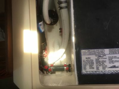
Photo (4) shows ! 6” of the new 1 1/2” ID SHIELDS RUBBER Poly X sanitation hose from the holding tank to the new Spears 1 ½” hose barb x 1 ½” hose barb elbow and another ~6” of the new 1 1/2” ID SHIELDS RUBBER Poly X sanitation hose from the new elbow to the macerator pump housing.
Photo (5) provides a clearer view of the new macerator pump installed higher up on the bulkhead than before, and I am now using the hose barb connection instead of the threaded portion of the pump housing. This will make removing the pump much simpler and cleaner when it’s time for maintenance in the future. (hopefully distant future). With the pump up higher, I had to rotate the 1” pump discharge 180 degrees so the 1” discharge hose from the pump now points down toward the hull instead of up toward the cover as it was originally.
Photo (6) shows the anti siphon valve and loop that is behind the seat cushion next to the Navigation Station.
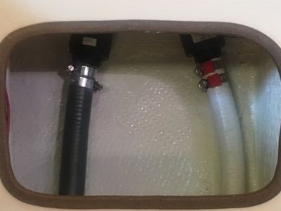
Photo (7) shows access to the flanged sea cock for the macrerator pump discharge.
PDF of This Write-Up
I've attached a copy of this complete write-up in a PDF format for reference. All links have been removed from the PDF.
