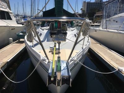
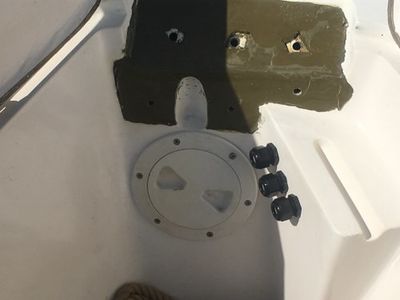
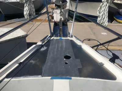
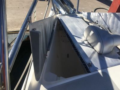
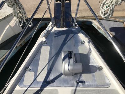
1987 MK 1 Catalina 34 Horizontal Windlass and New Double Doors
By Jon Windt; Della Jean
REVISION A – 9-19-2019 Section 7 was revised due to add photos and text for the wiring inside the anchor locker that was originally left out by accident.
REVISION B – 2-02-2021 Section 5 was revised due to purchasing 190 feet of chain instead of 200 feet of chain at 1.1 lbs per foot.
REVISION C – 3-05-2025 Section 8 Photos 55, 60, 61, 62, 63, 65 and 66 were revised to reflect replacing my Manson Supreme 35lb anchor with a Mantus M1 35 lb anchor.
NOTE - Before doing any projects, I highly recommend that you first go through the “Critical Upgrades” list and verify that your boat has all of the applicable items addressed. There is a link on the Message Board (copied here) entitled “CRITICAL UPGRADES – DO THESE OR ELSE!!!” that will take you to them. It is a good way to both learn your boat and make sure it is safe. Don’t put it off.
Contents
Original Anchoring System Description
I purchased my Catalina 34 in April 2015. She is a 1987 MK1, hull #493. The MK 1 design has a double door to access the inside of the anchor locker. There are no provisions for an electric or manual windlass that I could see. My boat came with two sets of ground tackle.
Primary Ground Tackle - consisted of 35 feet of very corroded 3/8” chain, 250 feet of very old ¾” 3 strand rode stored in the anchor locker, and a medium sized Danforth type anchor stored in the port cockpit locker.
Secondary Ground Tackle - consisted of 30 feet of good condition 5/16” chain, 150 feet of newer ½” 3 strand rode, and a small Danforth type anchor stored in the port cockpit locker.
Due to the condition of the chain I have not done any anchoring since buying the boat. I also had no interest in straddling the anchor well and hoisting the anchor, chain, and rode by hand.
Background
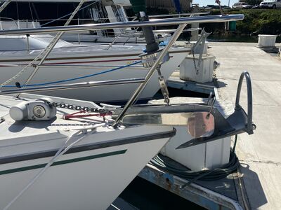
I am refitting my C34 for future short and extended cruising. A priority for me is positioning myself to have as many anchoring options as possible. This project is being done in two phases. The first phase was replacing the original small OEM bow roller and stemhead fitting with a more robust bow roller and continuous 3/8” thick SST stemhead fitting. The following two photos of the new bow roller and stemhead fitting are provided for reference.
With the bow roller upgrade completed, the next step is to install an electric windlass. I read the write ups in the Tech WIKI of what others had done to solve this problem. I had also looked at other boats. One that stood out to me was a Catalina 34 for sale in Hawaii that had a horizontal windlass installed on the deck above the anchor locker. They had removed the double doors and replaced them with two SST plates. One was an access door, and the other a fixed plate that the horizontal windlass was mounted to. I thought this was a very interesting approach that would maximize the space for chain and rode in the anchor locker, and make maintenance of the windlass easier.
This write up provides a summary of the electric windlass installation I did with photos, a cable planner that includes a schematic, and a parts list. I've numbered the photos to help with connecting the text to the associated photo.
My 1987 MK 1did not have a windlass or a provision to install a windlass (electric or manual), so for me this was a very complicated project. The steps were to choose between a vertical and horizontal windlass, develop a concept to mount the windlass, define how to wire it, decide where to put the up/down solenoid, breaker/isolator, helm switch, rode counter, receiver for the wireless remote, fuses, and other parts of the system. The windlass electrical system will tie in nicely with the wiring I had already run as part of my complete electrical upgrade completed in the 1st Qtr of 2016. Details for that are in a separate write-up titled “1987 MK 1 Catalina 34 Electrical System Upgrade” that I added to the “Electrical” section of the Tech WIKI.
As a final note, every boat is different. The routing, methods, and windlass type I used may not work on your boat or for your needs. This is only a summary of what I did, not as a manual of what you must/should do. This is one way, not the only way. Good luck and I hope you find this write up helpful.
Before Photos
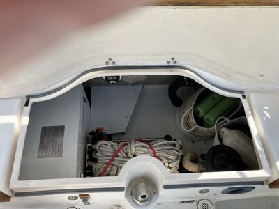
The following photos show the anchor locker before adding the windlass system upgrade. The text description for each group of photos is above them. They are provided to help give you a picture of the starting point.
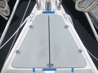
Photo (1) is the OEM anchor locker double doors when closed. The blue tape was used to define the boat centerline.
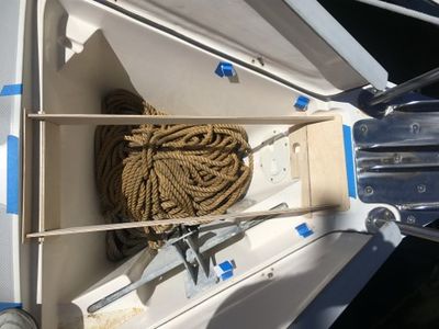
Photo (2) is the inside of the anchor locker with the OEM double doors removed. The ground tackle in the locker is the ¾” 3 strand and 35 feet of 3/8” chain, plus the 30 feet of 5/16” chain and 150 feet of ½” 3 strand anchor rode. I did this to get an idea of how much I could put in the locker. On the starboard side of the locker is the small Danforth type anchor. This will be stored in the port cockpit locker as a back-up, not in the anchor locker.
The Design Goals
- Maximize the space inside the anchor locker for chain and rode.
- Maintain two locker doors to access inside the anchor locker.
- Be able to raise and lower the anchor single handed safely.
- Be able to know how much chain is out or returned to the anchor locker from the helm.
- Locate all components to be easily accessible and serviceable with minimal effort.
Choosing A Windlass
Like most topics related to a boat, there isn’t a simple choice. Key decisions I felt were Type, Size, Power Up and Down, Retrieval speed, Free fall capabilities, Chain and Rope Gypsy, Brand.
TYPE - The two basic types are VERTICAL and HORIZONTAL. Vertical and Horizontal are defined by the shaft orientation that rotates the gypsy/drum. Some background on each:
VERTICAL – When installed the motor shaft orientation is up and down (vertical) so the gypsy rotates in a horizontal direction. The motor and gearbox are installed under the deck. A few but not all Pros and Cons are listed as follows:
PROS –
- The motor and gearbox are out of the weather.
- Torque is horizontal so the load is absorbed by more of the boat deck surface.
- Most popular because of a lower more aesthetic deck profile.
CONS -
- Being below deck, installation and maintenance are more difficult.
- If installed in the anchor locker corrosion and maintenance may be more of an issue.
- Because the rode makes a 180 degree turn around the gypsy and another 90 degree turn to feed into the locker there is a tendancy to have more snags and hang ups than horizontal windlass.
- Requires a fall of 18 inches above the rode pile which reduces the amount of ground tackle that can be carried.
- If installed in V-berth, reduces storage space and will need to build a aesthetic cover.
HORIZONTAL – When installed the motor shaft orientation is horizontal so the gypsy rotates in a vertical direction. The motor and gearbox are installed on top of the deck.
PROS –
- Easier to install and maintain.
- Less prone to snags and hang ups than a vertical windlass.
- Requires a fall of 8 inches above the rode pile which allows the amount of ground tackle to be maximized.
- Because the rode makes a 90 degree turn around the gypsy and feeds into the locker there is less of a tendancy to have snags and hang ups than a vertical windlass.
CONS -
- Being on/above deck, some feel the aesthetics are undesirable.
SIZE - The pulling power or load capacity required of a windlass is hotly debated. Windlasses are not intended to pull a boat against a 25-knot wind and 2' chop with the engine in neutral. They are not designed to break out a heavy anchor under 3' of hard sand. They are designed to weigh an anchor and rode that is not under strain and to provide enough tension to break out a firmly set anchor. At the end of the day, it is the engine’s power that should be used to move the boat upwind, and it is the motion of the boat that should break out the anchor — not the windlass. Therefore the strain on the windlass should be limited to the hanging weight of the anchor and rode.
However, I’ve been told that manufacturers use the total weight of the ground tackle because many boaters don’t make proper use of their boat’s power when raising the anchor, so the actual working load is often much greater than the hanging weight of the anchor and rode. Therefore, manufacturers tend to recommend windlasses with hefty pulling power so that you have the capacity to weigh anchor even if your engine is out or it is already running at full capacity or your anchor is firmly stuck.
Sizing the windlass varies by windlass manufacturer. Most windlass manufacturers define the “working load” as the combined total weight of the anchor, chain, and rode. I plan to carry a 35 lb anchor, 190 feet of 5/16” G4 HT chain (1.10 lbs per foot), and 200 feet of 5/8” Yale 8 brait rode (.10 lbs per foot). The total weight for this set up would be 35 + 209 + 20 = 264 lbs.
- Lewmar says use 4 x the total ground tackle weight to identify the proper size of their windlass. So I would need a Lewmar windlass capable of a 1,056 lb working load.
- Maxwell says use 3 x the total ground tackle weight to identify the proper size of their windlass. So I would need a Maxwell windlass capable of a 792 lb working load.
POWER UP and DOWN – I’m getting a windlass to make retrieving the anchor and rode simpler. I think dropping the anchor in a controlled manner is also important for safety so wanted to be able to power the anchor and rode both up and down.
RETREIVAL SPEED – Retrieval speed is important for urgent or emergency situations where you want to get the anchor up and get out of the area fast.
FREE FALL CAPABILITY – Free fall capability is important for urgent or emergency situations where you want to get anchored fast.
CHAIN and RODE GYPSY – I wanted to carry both chain and line anchor rode so wanted a windlass and gypsy that can do both.
BRAND – Brand is important for availability, quality, price, aesthetics, and the pulling power or load capacity required. The difference between Lewmar and Maxwell “working load” for example can put you into the next larger size windlass.
MY CHOICE – Experienced cruisers I talked to all preferred the horizontal type windlass for durability, and ease of maintenance. A vertical windlass required more free fall distance for the chain/rode, and the motor would protrude far into the anchor locker. I decided to go with a HRC FF8-8 horizontal windlass from Maxwell. It is compact, powerful, good reputation, and I think a good fit for the MK 1 anchor locker.
At the time I was making this decision, Defender had a great sale on so was able to get the electric windlass for ~ half price plus it came with the up/down solenoid, up/down helm switch, and a wireless remote up/down switch (like a key fob for your car door locks). I also purchased an Auto Anchor 150 rode counter that was also on sale at a steep discount. Can’t beat good timing.
New Anchor Locker Doors and Windlass Support
To make the new anchor locker doors and windlass support. I chose to go with aluminum and save my OEM fiberglass doors as a just in case backup. For the windlass support I used 5086 aluminum which is the grade of aluminum used to make the hulls for aluminum boats. It is very strong and highly corrosion resistant and is often the material of choice for bare aluminum hulls. For the new doors I used 6061 aluminum mostly because the fabricator had scrap material that could be used for this small (to him) project very cheaply.
This design consists of two main parts. The center windlass support structure assembly, and the port and starboard anchor locker doors. The center windlass support structure assembly provides support for the windlass. It does this vertically by use of fore and aft ¼” thick aluminum stiffeners that will be welded to the underside the ½” aluminum top, and by a combination of a tight fit to the boat and eleven bolts attaching the assembly to the boat.
NOTE: All of the bolts are in shear, none are in tension.
The tight fit will be accomplished by using a structural epoxy called Splash Zone which will fill any voids between the assembly and the boat. Sort of a liquid shim that is also structural. The tight fit allows the use of the boat structure as a component of the support system, reducing the critical nature of the eleven fasteners. A snubber will be used to carry the load while at anchor, so the loads on the windlass are less than 275 lbs. in its worst case which is weighing anchor in 50 feet of water.
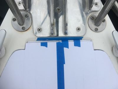
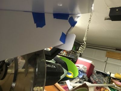
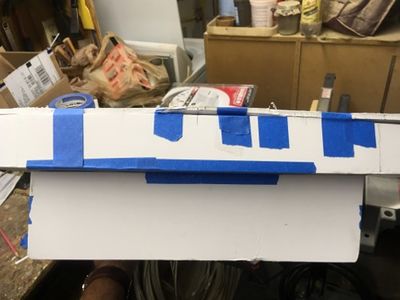
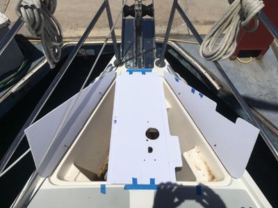
I made a couple of mock-up versions out of 3/16” foam board to work out the details of the design. Photos (3) and (4) show the foam board cut to fit the anchor locker opening.
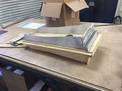
Photos (5) and (6) show some of the underside pieces of the windlass support.
Photos (7) and (8) show the final version of foam board mock up with the two new anchor doors, holes for fastening the windlass to the support structure, the hawse pipe, the rode counter sensor cable, and the windlass motor wires. The notch in the starboard anchor locker door is to avoid an interference with the windlass motor which is mounted horizontal.
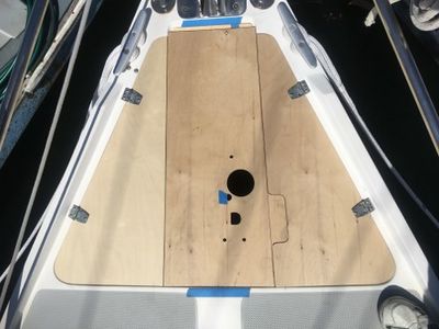
After roughing out the design in 3/16” foam board, I created a more complete and accurate mock-up using ¼” plywood. This more accurate plywood template is for the fabricator to use to cut the metal parts for welding. To hold the plywood pieces together during construction and fit up, I used a hot glue gun to bond the pieces together. By using a hot glue gun, the individual pieces are easy to separate without damage. This is important so they can be used as the template to cut the metal parts. This helps reduce the labor cost.
Photo (9) shows the plywood version of mock up made from the foam board mock up.
Photo (10) shows the stringers and interface plates underneath the plywood support structure.
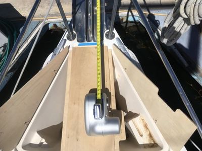
Photos (11) and (12) show the plywood mock with the windlass attached. The anchor locker doors are hinged in the same way as the OEM fiberglass double doors were. When closed they rest on a 1 inch flange that is ¼” below the top of the support structure. The 1 inch flange is the lighter color wood on each side of the support structure in photo (11). The tape measure is being used to ensure the gypsy lines up with the bow roller. A horizontal windlass is more sensitive to alignment of the chain with the bow roller than a vertical windlass.
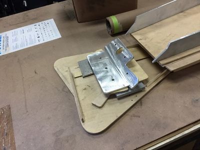
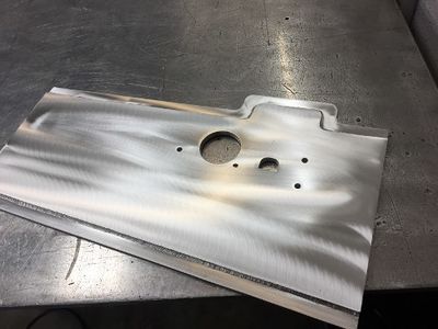
With the plywood mock up complete, the next step is to fabricate the assembly out of aluminum. In photo (13) the angled interface plate matches up to the forward surface of the deck and anchor locker. It is shown just before being welded onto the stiffeners shown on the right side of the photo. On the left side of the interface plate you can see three holes in a line. These will be used to thru bolt the windlass support structure into the hull with three 5/16” SST bolts and a ¼” backing plate.
On the right side of the interface plate, you see three additional smaller holes. These will be used to thru bolt the windlass support structure into the anchor locker wall with three 1/4” SST bolts and three ¼” backing plates.
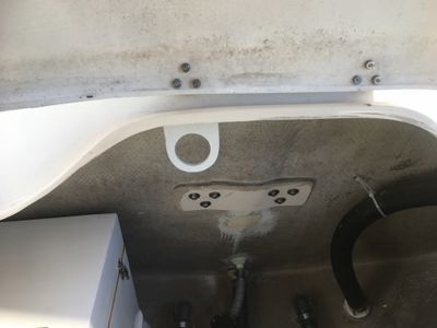
The oblong hole on the right side of the interface plate is to provide clearance for the recess in the anchor locker for the Danforth type anchor. It won’t be used for an anchor anymore, but may come in handy for something else in the future.
In photo (14) the aluminum windlass support structure is being fabricated. You get a good look at the recessed flange that the doors will sit on in this photo.
In photo (15) you get a good view of the aft interface support that will both rest on the anchor locker recess near the top of the locker, and the vertical wall of the anchor locker just forward of the aft cabin. There are five holes in the vertical plate for five ¼” lag bolts that will be threaded into the aft anchor locker wall and into the ¾” plywood bonded to the hull behind the teak plywood in the aft cabin.
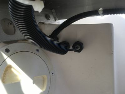
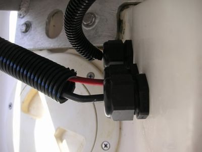
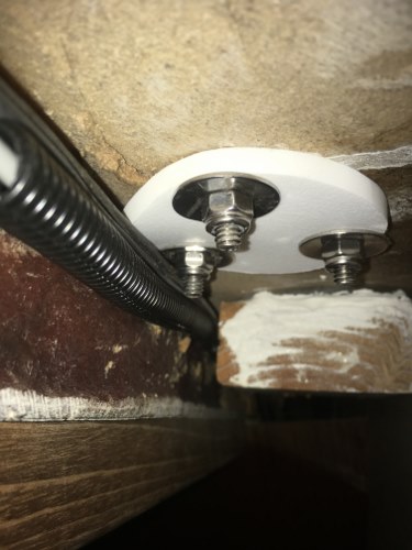
With the center support structure fabrication complete, it’s ready for its’ final fit up with Splash Zone epoxy. I used mylar shipping tape as a release agent on the surfaces that the Splash Zone would be in contact with so the part would not stick to the epoxy. Photo (16) shows the dried Splash Zone epoxy at the forward end of the anchor locker. The three 5/16” bolt holes, and three ¼” bolt holes are also visible. Silicone will be used to seal around the bolts so they don’t leak. On the starboard wall of the anchor locker are three thru deck wire seals. I used these for a water tight seal around the motor cables and the rode counter sensor cable. The deck wire seal closest to the beckson plate is for the rode counter sensor cable. It passes thru the seal into a split loom and takes a right turn into the V-berth overhead between the deck and the covers. The motor cables go thru the two remaining wire seals into a split loom and turn down into the V-berth below the mattress platform.
Photo (17) shows the dried Splash Zone epoxy at the aft end of the anchor locker. The five 1/4” bolt holes are also visible. Silicone will be used to seal around the bolts so they don’t leak.
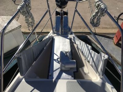
Photos (18) and (19) show the finished aluminum assembly installed. Sikaflex 291 was also used around the edges of the center support structure to give a “belt and suspenders” finish to the install. The doors have a slight crown to match the curve of the deck. The crown was put in by clamping a piece of wood on each side of the door in a vise and “eye balling” the bend. It took a few pulls to get it to match. The blue tape has centerline marks on it and was used to take all measurements and alignment throughout the entire process.
Another important feature are the two stiffeners attached to the underside of each door. I don’t know what they are made of. They are a composite material that the fabricator had as scrap and gave it to me. They are attached with countersunk SST screws and rest on the lip at the top of the anchor locker. This gives the 1/8” thick door a very solid feel when standing on them. Photo (20) shows the port door open so you can see the door stiffeners.
Photos (21) and (22) show the finished mechanical part of the project. To get the two different aluminum materials to match aesthetically I scrubbed them with a green 3M pad and lemon oil. Messy but works great to visually blend the two materials. Finally, to avoid slipping I added two strips of clear 3M non skid tape on both sides of the windlass.
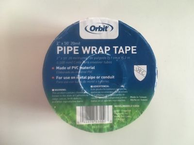
FYI - To insulate the SST door hinges and the pad eye from the aluminum windlass support structure and doors I used 20 mil PVC pipe wrap tape that is cut to match the shape. Photo (23) shows the roll of tape.
Wiring Runs
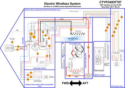
Below is a copy of the wiring schematic to help familiarize you with the system. A PDF of the schematic is available at the end of this write up.
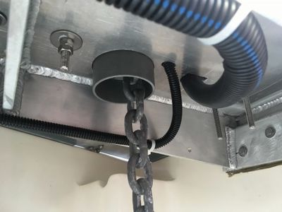
Photo (24) shows the windlass motor wires exiting the aluminum windlass support then running on either side underneath the aluminum windlass support in split looms. I ran them on different sides to avoid any electrical interference from the windlass motor affecting the rode counter signal.
Photo (25) shows the windlass motor in the larger split loom and rode counter in the smaller split loom running underneath the aluminum windlass support to the forward side of the anchor locker in split looms. Photo (26) shows the wires passing through watertight cable glands held tight to the locker wall with the backing nuts provided. From here, the windlass motor wires run down along the hull and underneath the mattress platform into the V-berth. The rode counter wires run between the underside of the deck and the removable cover along the starboard side.
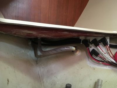
The wiring from the windlass motor travels from the anchor locker down and underneath the mattress platform in the V-berth. The larger split loom in photo (26) has the windlass motor cables and is coming from the anchor locker. The smaller split loom has the wires from the wireless remote receiver located in the overhead on the port side.
Photo (27) shows the windlass motor cables coming from the cable glands in the anchor locker. The smaller split loom here is not the rode counter. This one carries the wires from the wireless remote receiver located in the overhead on the port side.
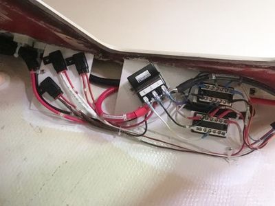
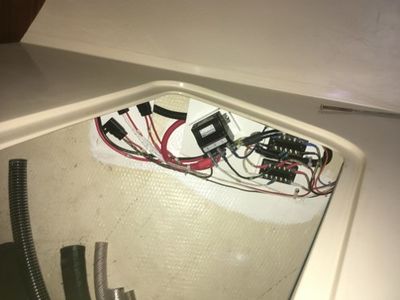
For the landing the wiring, I created a breadboard to attach the up/down solenoid, two dual buss bars, and the in-line fuses. It is located under the V-berth mattress platform. It is epoxied to the hull and underside of the mattress platform with West Systems Six10 thickened epoxy adhesive. Photo (28) shows the finished assembly.
Photo (29) shows the access to the finished assembly from the forward hatch in the mattress platform. Changing the fuses or any troubleshooting can be easily done from above so it isn’t necessary to climb into the space under the platform.
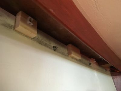
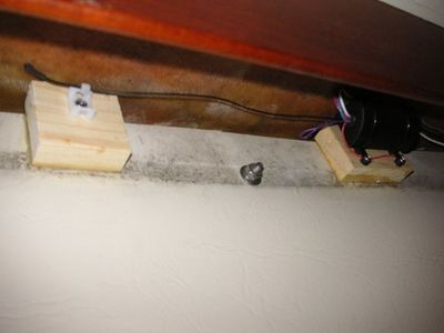
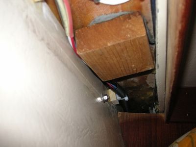
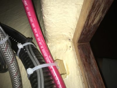
To minimize drilling holes into the boat, I cut ¾” thick wood blocks into 1 inch squares. I predrilled holes needed to mount cable mounting ties or a component before bonding to the hull. To bond these wood blocks to the hull I used West Systems Six10. Photo (30) is an example of the wood blocks installed. I used this method when I needed to add a wire tie or component instead of drilling into the hull, deck, or a bulkhead.
(FYI - Pre-drilling is important because some areas you can’t get a drill and drill bit into the space to drill a hole.)
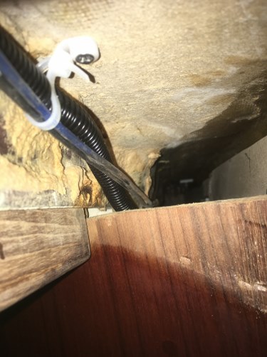
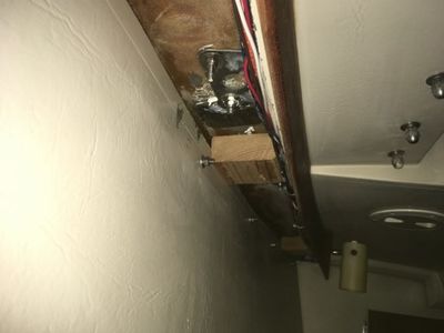
The wiring for the wireless remote receiver is located overhead on the port side of the V-berth between the underside of the deck and the removable cover as shown in photo (31). The black wire going left in the photo is the antennae for the receiver.
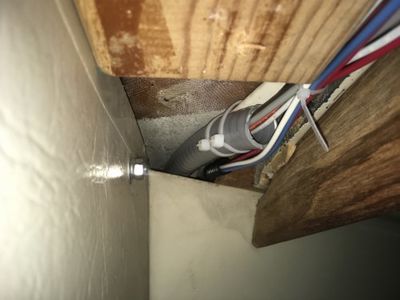
In photo (32) you can see the wireless remote wires from the receiver going to the dual buss bar on the breadboard under the mattress platform. The beginning of the split loom is visible in the lower right with a cable tie around it.
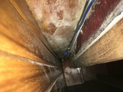
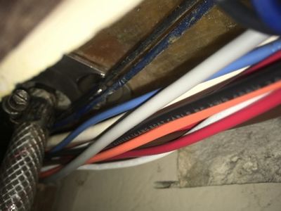
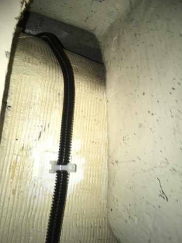
Photo (33) shows the split loom with the rode counter sensor cable coming from the anchor locker. Photo (34) shows the split loom traveling past the ¼” backing plate for the starboard aft pulpit stantion. Photo (35) shows the sensor cable passing into the salon area.
Photo (36) shows the sensor cable continuing to run in the starboard overhead raceway in the salon. It continues all the way to the aft locker where it finally connects to the digital readout.
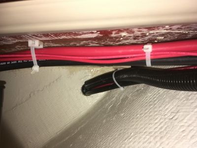
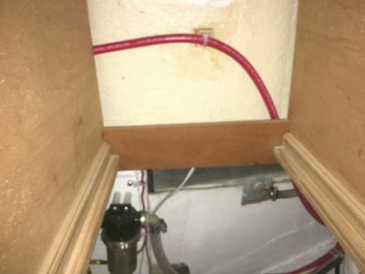
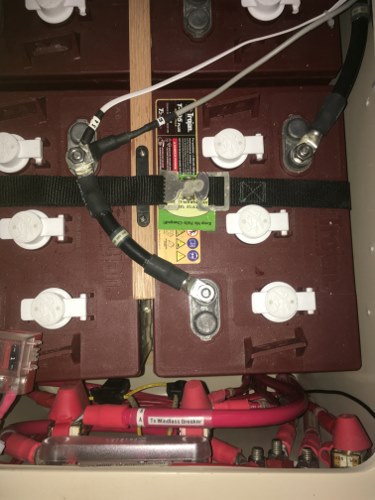
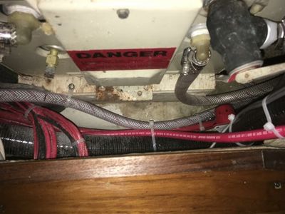
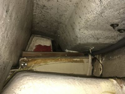
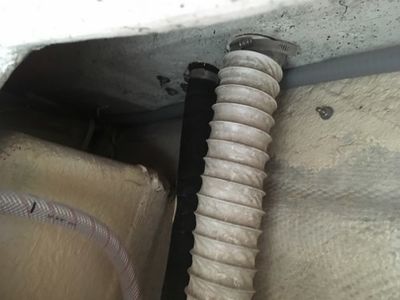
Photo (37) shows the 1 AWG cables connecting the breaker/isolator, the negative house buss bar, and the split loom containing the 16 AWG wires connecting the helm switch, and rode counter as they pass under the starboard settee from the V-berth. They continue past the starboard water tank as shown in photo (38). (The red and black cables and wires traveling right to left are for the reserve battery located just outside of the photo. They not related to this project).
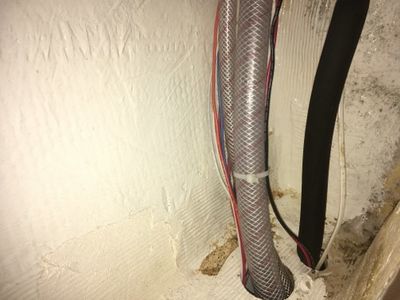
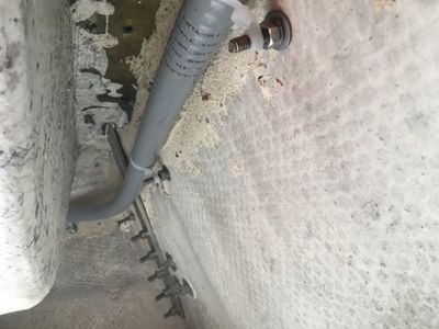
The 16 AWG wires connecting the helm switch, and rode counter continue past the water tank and turn up to follow the starboard water tank fill hose as shown in photo (39). When they reach the underside of the deck they turn aft going past the water tank vented stantion shown in photo (40) and continue traveling to the aft locker where they go to the helm switch and the rode counter digital readout.
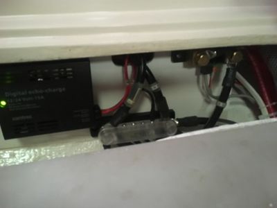
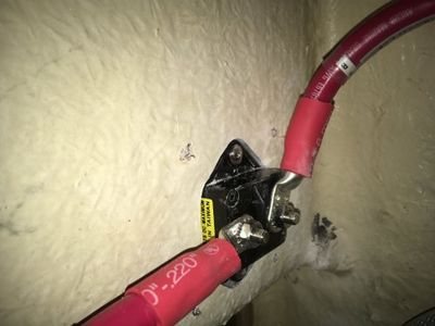
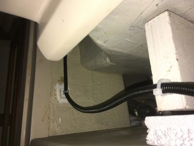
The 1 AWG negative cable from the up/down solenoid goes to the house negative buss bar shown in photo (41). The positive 1 AWG cable from the up/down solenoid travels past the negative buss bar and turns vertically under the galley sink and behind the galley drawers as shown in photo (42).
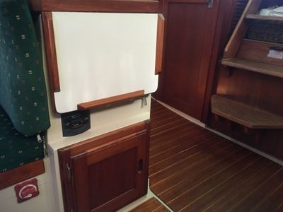
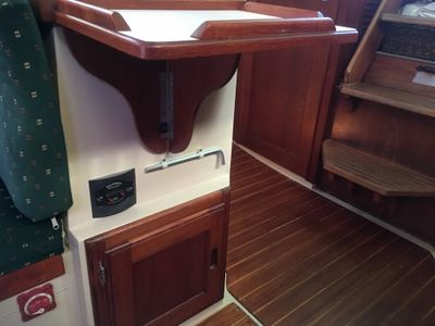
It continues along the bulkhead under the galley sink, past the water heater to the isolator/breaker located on the vertical bulkhead at the end of the galley counter. Photo (43) shows the back side of the isolator/breaker. The red cable on the left is from the house bank. Photo (44) shows the front side of the isolator/breaker. Photo (45) shows the counter extension opened for a better view of both the isolator/breaker, and the windlass wrench that is used to loosen the clutch for maintenance.
The power to the breaker/isolator comes from the house bank as shown in photo (46).
From the house bank the cable travels along the bilge hose then up to the breaker/isolator as shown in photos (47) and (48).
With the breaker/isolator complete, I’m going to turn back to the wiring to the helm switch and the rode counter digital readout. The helm switch and rode counter wires and sensor cable enter the aft cabin from the galley cupboard above the stove/oven as shown in photo (49).
They continue in this overhead raceway as shown in photo (50) until they exit the aft cabin. At this point the rode counter 16 AWG wires and the sensor cable enter a ¾” flexible conduit that carries them all the way to the digital readout. The helm switch wires enter a ½” split loom and turn towards the helm pedestal. See photo (51)
From the split loom the helm switch wires travel down the side of the aft cabin hanging locker as shown in photo (52).
From there it continues on to the underside of the cockpit as shown in photo (53) across to the underside of the pedestal where it enters the port side 1” tube as shown in photo (54). It then runs up to the helm station and connects to the up/down switch mounted there ending this circuit. See photo (55).
The 16 AWG rode counter wires and sensor cable run through the flexible conduit that can be seen on the right side of photo (56). It continues past the aft water tank fill hose and engine compartment vent hose as shown in photo (57), and continues to the center of the aft locker where it ends as shown in photo (58)
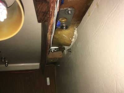
The digital readout needed a bracket to hold it so I made one out of ¼” plywood. To attach it to the boat I changed the aft locker seat hinge screws to 1 ¼” long screws. This allowed me to attach the wood bracket securely without drilling any new holes.. See photo (59).
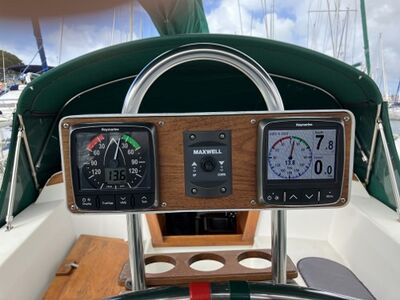
Photo (60) shows the digital readout installed. Photo (61) shows the view of the rode counter when standing at the helm. It would be better if the numbers in the LED display were brighter, but the black numbers are very visible in person and the display is out of the elements.
Anchor, Chain, and Rode Installed
Photos (62) and (63) show the finished project with the Mantus M1 35 lb anchor installed on the starboard bow roller. The port bow roller is for back up or to use with a mooring line. If I need to use two anchors off the bow I plan to have them in line not port and starboard. If I need to secure the anchor to the deck, I use a Suncor grab hook attached to a red piece of Dyneema. The hook attaches to the chain near the shackle. The red Dyneema then passes through a SST pad eye that is through bolted to the windlass support structure and back through the slot in the anchor to secure the anchor to the deck if needed in rough weather.
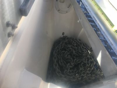
Photo (64) shows the 210 feet of Yale 8 brait and 180 feet of 5/16” G4 HT galvanized chain loaded into the anchor locker. For reference, the distance from the deck to the top of the chain pile is approximately 17”. When loading the chain and rode into the anchor locker it is very important to load the rode and chain thru the windlass to avoid any twists in either the rode or the chain. A twist in the chain could cause the windlass to jam.
Photos (65) and (66) show a high tensile shackle installed on the end of the anchor blade. I wanted to be able tie a line to this shackle with a float of some kind on the other end. There are two reasons for this. First the float will identify where the anchor is so I can drive up to it. Second once the chain is vertical the line will be fastened to the forward cleat and used to free the anchor before hoisting with the windlass. This should avoid fouling the anchor under rocks or a tree.
Parts Used
I've attached a copy of the parts list in both an Excel and PDF format. The parts list contains the part name and number. This is provided as a reference only, there are lots of choices out there.
CAUTION - The wire and cable lengths provided are for my design and the cable/wire run choices I made. They are provided as a reference only. Your lengths may differ, measure for your application.
File:Replacement Parts Electric Windlass 2-20-18.xlsx
File:Replacement Parts Windlass 2-20-18.pdf
Schematic
I've attached a copy of the wire and cable schematic in PDF format to be used with the cable planner below. This is provided as a reference only, your design may result in a different approach with different results.
CAUTION - The wire and cable lengths and gauges provided are for my design and the cable/wire run choices I made. They are provided as a reference only. Your lengths and gauges may differ, measure for your application.
File:Della Jean Windlass Upgrade Schematic Rev B.pdf
Cable Planner
I've attached a copy of the cable planner with cable lengths, voltage drop, etc.. in both an Excel and PDF format. This is provided as a reference only, your design may resukt in different values.
CAUTION - The wire and cable lengths provided are for my design and the cable/wire run choices I made. They are provided as a reference only. Your lengths may differ, measure for your application.
File:Windlass Cable Planner 2-20-18.xlsx
File:Cable Planner 2-20-18.pdf
PDF of This Write-Up
I've attached a copy of this complete write-up in a PDF format for reference. All links have been removed from the PDF.
File:Catalina 34 Horizontal Windlass and New Double Doors Rev C 3-05-25.pdf


