1987 MK 1 Catalina 34 Adding A 2nd Electric Bilge Pump
By Jon Windt; Della Jean
NOTE - Before doing any projects, I highly recommend that you first go through the “Critical Upgrades” list and verify that your boat has all of the applicable items addressed. There is a link on the Message Board (copied here) entitled “CRITICAL UPGRADES – DO THESE OR ELSE!!!” that will take you to them. It is a good way to both learn your boat and make sure it is safe. Don’t put it off.
Contents
Original Bilge System Description
I purchased my Catalina 34 in April 2015. She is a 1987 MK1, hull #493.
The bilge pump system consisted of one Whale brand manual bilge pump and one Rule 1500 Gallons Per Hour (GPH) electric bilge pump.
The manual bilge pump has a 1 1/2" corrugated hose led aft from the aft bilge section to a Whale pump mounted in the aft lazarette. The discharge for this pump is located on the centerline of the vessel at the lowest point on the transom.
The Rule 1500 electric bilge pump has a 1 1/8” corrugated hose led aft to the transom where it discharges in the upper starboard corner of the transom near the split back stay chain plate. The hose consisted of several sections of two different types of hose and 3 in-line check valves attached with SST hose clamps. Two sections of hose were press fit together without any hose clamps and as a result had minor leaks. The electric pump is controlled by a 10 amp breaker with an auto/on/off switch arrangement located on the Main Distribution Panel.
FYI: Although rated for 1500 GPH, actual flow depends on the rise from the pump to the discharge thru hull. Per the installation guide for RULE bilge pumps, the Rule 1500 with a 5 foot rise will flow ~ 875 GPH with a 1 1/8" hose.
Background
I am refitting my C34 for future short and extended cruising. A priority for me is reducing failure modes. Popular opinion is that after the integrity of the hull, the integrity of the bilge pumping system is most critical. My current set up with one manual pump and one electric bilge pump provides no redundancy so for me is not a robust enough system. Three “common” failure modes are an unexpected failure of the engine water exhaust hose causing the engine to fill the hull with water or, the single electric pump or switch fails, or a sea cock or thru hull fails before you realize the failure has occurred. While a single 1500 Gallons Per Hour (GPH) pump (which doesn’t pump 1500 GPH as noted earlier), may be able to keep up with the ingress and provide you time to stop/slow the flow of water, the safety margin of the system can be improved by increasing the number of pumps.
Adding additional bilge pumps is a choice I’m making. The cost of ~$335 for the Rule 3700 pump, switch, bracket material to mount them, hose, clamps, and vented loops for me , is a small price to pay for the peace of mind, and increased reliability. As an FYI – I may add a 2-way selector valve to the engine raw water inlet before the filter with a hose to reach into the forward berth section. This would give me a high flow mechanical pump for a true emergency for minimal cost with the turn of the valve.
FYI: Regardless of how good the bilge pump system is, it is dependent on an electrical and battery system that can run them for the necessary period of time. I’ve recently completed a major electrical upgrade of the batteries, charging system, and core electrical systems so believe I’ve got the electrical system covered.
This write up provides a summary of the bilge system upgrade I did with photos, plus a parts list. I've numbered the photos to help with connecting the text to the associated photo.
This was not a very complicated project, but like most projects I’ve done on this boat, nothing was straight forward the first time around. It required lots of thought and decisions each step of the way. All in all, I ran ~ 25 feet of new smooth bore 1 1/8” bilge hose, and about 25 feet of new smooth bore 1 1/2” bilge hose. I added a second Rule 3700 GPH pump with a separate float switch connected to a dedicated 25A on/off/AUTO breaker on my Main Distribution Panel. The wiring had already been run as part of my complete electrical upgrade completed in the 1st Qtr of 2016. Electrical details for that are in a separate write-up entitled 1987 MK 1 Catalina 34 Electrical System Upgrade located in the "Electrical" section of the Tech WIKI.
As a final note, every boat is different. The routing, methods, and hose lengths I used may not work on your boat. Please read this as a summary of what I did, not as a manual of what you must do. This is one way, not the only way. Good luck and I hope you find this write up helpful.
Before Photos
The following photos show the boat before adding the bilge pump system upgrade. The text description for each group of photos is above them. They are provided to help give you a picture of the starting point.
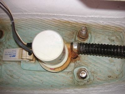
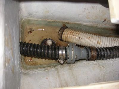
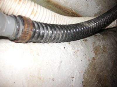
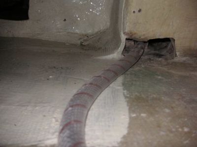
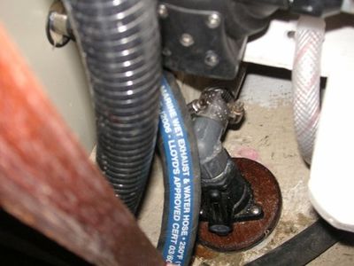
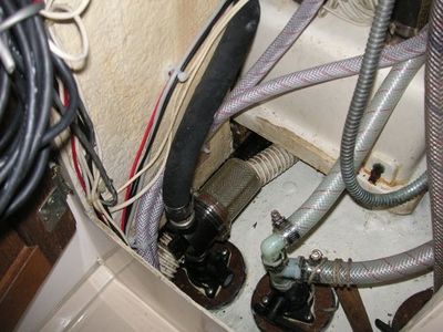
Photo (1) is the existing Rule 1500 pump and switch mounted on an ~ 5/16” raised surface glassed into the bottom of the bilge. Notice the severely rusted hose clamp. I was not able to loosen it so used my Dremel tool to cut the metal band to remove it. Photo (2) is the aft most bilge section. The 1 1/8” hose for the Rule 1500 and one of the in line check valves ran along the bottom of the bilge and through a ~2” hole in the port to starboard stringer to attach to the pump located in the center bilge section. Also in this bilge section is the end of 1 ½” manual bilge pump hose. It had a screen tie wrapped over the end to keep debris from being drawn into the hose and eventually the pump. The screen was torn and the hose clamp for the in-line check valve was rusted.
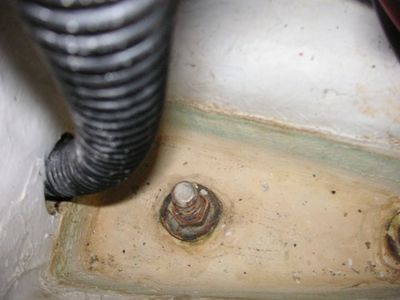
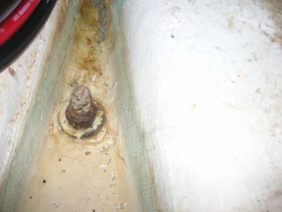
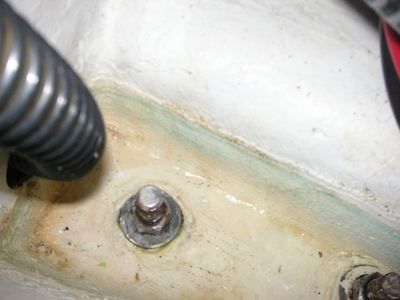
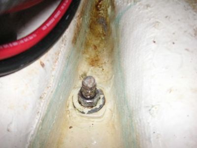
Photo (3) is the 1st keel bolt in the aft bilge section with the bilge hoses moved out of the way. Photo (4) is the 2nd keel bolt in the aft bilge section also with the bilge hoses moved out of the way. Both showed quite a bit of corrosion from the standing water that used to sit in this section. One of my first upgrades was to install a SST propeller shaft and change the packing gland material to a Gortex product. Now this section remains dry. Later in this write up are photos after I cleaned all the keel bolts With Davis brand FSR.
FYI – I’ve been told that Gortex can only be used with a SST shaft. Don’t know the reasons behind it, but you can’t use Gortex with a bronze shaft.
Photo (5) is the same bilge section but farther aft under the subfloor showing another rusted hose clamp on the 1 1/8” bilge hose. I point these out because this is the primary bilge pump system that could fail, even with a good pump and switch. I suggest you look at your bilge hoses and clamps, even if not planning to change anything.
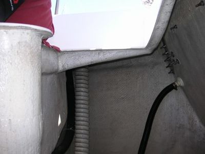
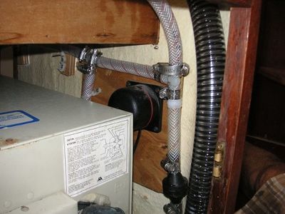
Photo (6) is under the aft cabin on the starboard side. The hose shown is the 1/2” fresh water supply line from the aft water tank going to the galley sink area where it connects into the main fresh water line with the starboard water tank prior to the fresh water pump. Previously I had run the starter, alternator out, and main negative cables through this opening. I found a way to route those cables more directly to the engine compartment. See photo (7). This routing change is both better electrically, and it gets the hot and cold fresh water hoses to the head sink out of the engine compartment which then frees up this opening to run the 1 1/8” bilge hose for the Rule 1500.
Photo (8) shows the thru hull for the 1 1/8” bilge hose. The thru hull is located high on the starboard side of the transom near the split back stay chain plate.
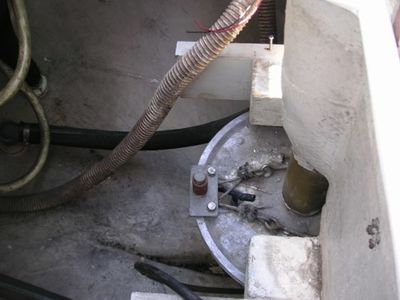
Photo (9) shows the manual bilge pump hose in the aft lazarette with the propane locker and shelf protecting the radial removed. The manual bilge hose discharge thru hull is very low on the transoms centerline just barely out of the photo. The two light colored hoses are the vent lines from the propane locker moved out of the way to get in this area to work.
The Design Goals
- Locate all components to be easily accessible and serviceable with minimal effort.
- Add a Rule 3700 electric bilge pump to add pump capacity and have redundancy in the bilge pump system. The Rule 3700 with a 3 foot rise will flow ~3,000 GPH with 1 1/2" hose. Total flow with both pumps running is ~3875 GPH or ~ 64.5 gpm exiting the boat.
- Remove all in-line check valves and use vented loops as an anti-siphon for the 1 1/2” bilge hose system, and to minimize run back into the bilge from the 1 1/8” bilge hose system.
- Remove corrosion from keel bolts.
- Size all hoses to match the pump exit and to be smooth bore inside for minimal flow resistance, and outside to make clamping more secure.
Rule 3700 Pump & Float Switch Installation
The location to install the larger Rule 3700 was limited by where the 1 1/2” hose could run. My preferred choices were the bilge section just aft of the mast step, and in the center bilge section where the Rule 1500 and switch were already located. I did not want to install it in the aft bilge section due to access and the hoses and electrical cables running in that area. The pump would have fit in the bilge section just aft of the mast step, but to connect the 1 1/2” hose to it would require drilling a large hole in the stringer. I believe this is a structural member so I did not want to drill a minimum 2 1/4” diameter hole in it. The challenge with the center section is leaving enough vertical distance for the Rule 1500 float switch to operate freely through its full range, and to ensure I could get to the keel bolts simply.
Several things had to be accounted for to not only install the pump and switch, but for them to work properly after being installed. Since the pump was the larger and more difficult piece to install, I used it as the primary feature. Determining the installed pump height was defined by four key features.
- Making sure the Rule 1500 float switch could operate its full range up without hitting the bottom of the new pump shelf.
- The top of the pump must be below the sub floor so the cover for the bilge could be installed.
- Be able to hold and get a wrench under the shelf to remove the lock nuts to move the shelf out of the way to access the keel bolts if needed.
- To be at least 1” away from the vertical edge of the bilge to minimize any impact the vertical edge may have to the pump when drawing water.
The new float switch had to be installed even with, or slightly above, the bottom of the installed pump. This ensures that when the switch is activated the pump is in water. If the float switch is below the bottom of the pump, it will activate the pump but the pump is not in water so will just use up the batteries. Don’t want that.
What I did was make two shelves out of 1/4” Starboard. One for the float switch, and one for the pump. They would each be fastened with screws and locknuts to mounting points made of 1 x 1 x 1/16” aluminum angle. The float switch will be installed in the bilge section just aft of the mast step, and the pump will be installed in the center bilge section over the forward two keel bolts.
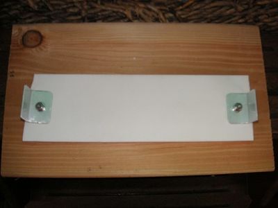
Photo (10) shows an example of the aluminum angle mounting method ready to be bonded into the bilge. To bond the aluminum angles to the bilge, I used West Systems 610 to epoxy. This is the float switch shelf with the aluminum angle fastened with SST #8 pan head machine screws, washers, and nyloc lock nuts at each end. The shelf is upside down to show the angles.
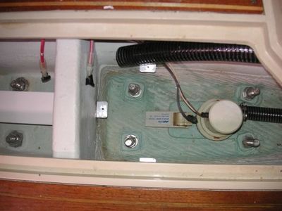
I then used each shelf to hold the angles snug against the bilge while the epoxy cured. This method also helped ensure the shelf was flat and at the right height in the bilge. Photo (11) shows the new float switch shelf installed in the bilge section just aft of the mast step, and the 3 aluminum angles to mount the new pump shelf over the keel bolts and Rule 1500 float switch in the center bilge section. The pump shelf was removed for clarity.
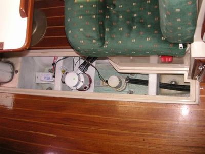
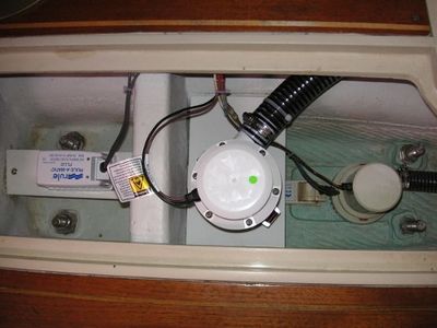
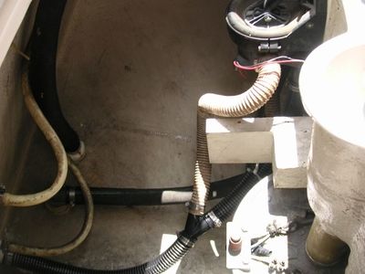
Photo (12) shows the new 2 electric pump bilge system with wires and hoses connected. Photo (13) is a closer view of the installed pumps. The 3700 1 1/2” bilge hose has a tie wrap attaching it to the shelf to pull it down to get a straight run to the pump connection.
As I mentioned earlier in the description, the keel bolts were very corroded in the aft section of the bilge due to the standing water that used to always be there. I used a product called FSR from Davis to clean them up. Photos (14) and (15) show the results. Not like new, but a lot better.
Vented Loop Installations
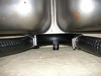
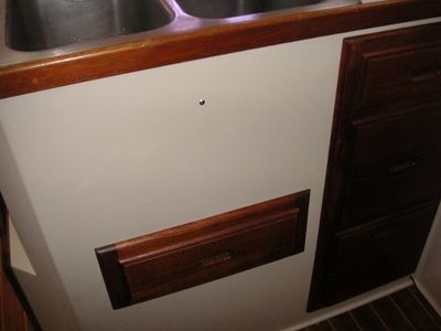
Photo (16) is a view from underneath the galley sink looking up to see the newly installed 1 1/8” vented loop and connecting to/from bilge hoses. The vented loop is up as high as it can go and still leave a small air gap between the top of the loop and the underside of the wood support for the galley countertop. I used my 90 degree drill adaptor to drill a hole for a #8 truss head SST screw to fasten the vented loop with a SST nyloc nut to the bulkhead. Photo (17) shows the screw head visible from the outside of the sink cabinet.
Photo (18) shows the 1 1/8” bilge hose running up the galley sink bulkhead from the Rule 1500 pump, over the sink drawer frame to the vented loop. Photo (19) shows the 1 1/8” bilge hose after the vented loop running down the galley sink bulkhead on the other side of the drawer frame to pass underneath the galley floor on its way to the are underneath the aft cabin.
Hose Runs To Aft Lazarette
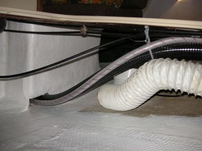
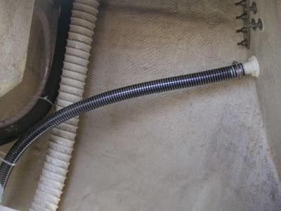
In photo (20) you can see the white manual bilge 1 1/2” pump hose. Tucked behind it is the Rule 3700 1 1/2” bilge pump hose. Previously the manual 1 1/2” and Rule 1500 bilge pump 1 1/8” hoses ran through this area making access to the raw water and head sea water sea cock handles awkward to open and close. This arrangement makes access very easy. In the lower left corner of the photo you can see the hot & cold fresh water supply hoses going to the head sink from the galley sink that I rerouted out of the engine compartment.
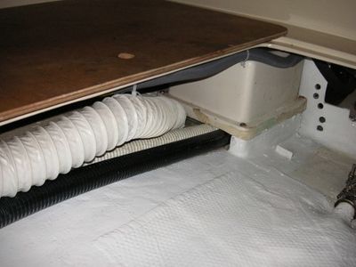
Photo (21) is taken underneath the aft cabin with the mattress and wood cover removed. The air vent lines are moved out of the way for clarity. The left side of the photo you can see the 1 1/2” bilge hoses running underneath the Aqualift muffler. It is a snug fit, but they both fit without putting pressure on the muffler. On the right side of the photo you see the 1/2” fresh water supply hose from the aft tank and the 1 1/8” bilge pump hose from the galley sink area.
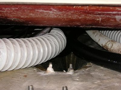
Photo (22) is a closer view of the 1 1/2” hoses passing under the Aqualift muffler.
Photo (23) is a closer view of the water supply hose and the 1 1/8” bilge pump hose.
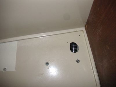
Photo (24) shows a hole I needed to drill into the subfloor. It is in the corner where the fiberglass bulkhead before the aft cabin mattress and the teak engine compartment bulkhead meet. The hole was needed because the area under the sub-floor needed some grinding to enable the 1 1/8” hose to slide through.
Photo (25) shows the bilge pump hoses, and the large air vent hoses passing from under the aft cabin to the aft lazarrette under the aft water tank.
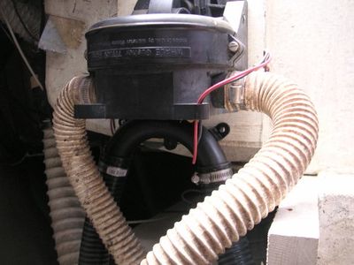
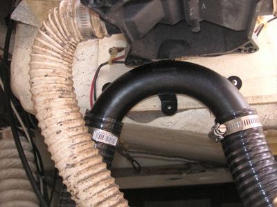
After the hoses leave the aft cabin and enter the aft lazarette they run port and starboard. In photo (26), the 1 1/2” bilge hoses run port and connect to the manual Whale pump and the new 1 1/2” vented loop I added just behind the Whale pump. 4.
Photo (27) is a closer view of the installed 1 1/2” vented loop.
Photo (28) shows the Whale manual and new Rule 3700 electric bilge pump discharge hoses tied together and connecting to the 1 1/2” thru hull at the bottom of the transom they both now share.
In photo (29), the 1 1/8” bilge hose from the Rule 1500 runs to starboard and connects high on the transom near the backstay chain plate. When I tested the system, water shot straight out of the thru hull approximately 6 inches beyond the transom.
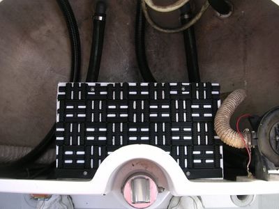
Photo (30) is of the wood cover in the aft lazarette protecting the radial from damage. I removed the propane locker and installed a non skid mat so this can be used as a step to get into the lazarette easier. I will be making a new propane locker with one 11# tank for the galley and one 5# tank for the BBQ. I will be installing it in the aft lazarette on the starboard side as my next project.
Main Distribution Panel
Photo (31) shows the Main Distribution Panel with both bilge pump breakers turned on. The bilge pump breakers are directly below the Smartgauge battery monitor. The Rule 1500 on/off/Auto breaker is first and the Rule 3700 on/off/Auto breaker is second. The Rule 1500 is labeled “Bilge Pump 1” and has a 10A breaker. The Rule 3700 is labeled “Bilge Pump 2” and has a 25A breaker.
Parts Used
I've attached a copy of the parts list in both an Excel and PDF format. The parts list contains the part name and number. This is provided as a reference only, there are lots of choices out there.
CAUTION - The hose lengths provided are for my design and the hose run choices I made. They are provided as a reference only. Your lengths may differ, measure for your application.
[Replacement_Parts_2nd_Electric_Bilge_Pump_08-19-16.xlsx]
[Replacement_Parts_2nd_Electric_Bilge_Pump_08-19-16.pdf]
PDF of This Write-Up
I've attached a copy of this complete write-up in a PDF format for reference. All links have been removed from the PDF.
