Mk I Windlass Installation Pictorial and Q&A
Mike Smith Breezer (#688)
Here are details on Mike Smith's windlass project for his 1988 Mk I C34, "Breezer" (#688).
An interesting Q&A between Mike and Mark Elkin follows.  (And see Mark's related Mk I Windlass Installation project).
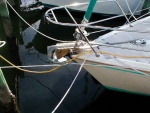
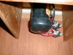
The windlass straddles the forepeak bulkhead, with the chain rode dropping down into the anchor locker and the windlass motor and electrical connections inside the forepeak protected from the weather. Battery is mounted beneath the starboard forepeak area just forward of the hanging locker. Circuit breaker and additional remote control are installed there also.
- Click on thumbnails to see larger picture
Mike's project brought lots of questions to Mark Elkin, so here's the body of an e-mail exchange regarding those questions.
Mark: Mike, these descriptions are good for clarifying the pictures. Together they provide a lot of clarity about the final installation. But I now wonder about the installation process and various "hidden" details. Could you answer a some questions related to the installation process itself?
Mike: My diesel mechanic helped me out a lot with the installation and it is always a good idea to have a pair of experienced eyes around when doing a project like this. We even fabricated a plywood mock-up to try everything out first!
Mark: What factors made you decide on this Simpson Lawrence model verse other vertical windlasses?
Mike: My mechanic was visiting relatives in the Tampa/St Petersburg area where the Simpson-Lawrence dealership is located. Since he insisted that I buy the chain (200' 5/16) from the manufacturer of the windlass - regardless of who that was - all other variables being equal, Simpson-Lawrence was the geographical choice! I wasn't about to pay the shipping costs for the chain! He picked them both up on his visit and was able to talk to the factory rep in person about the installation at the same time.
Mark: How easy/difficult was it to cut through the forepeak cabin roof where the windlass is mounted? Did you use a jigsaw or a hole-cutting drill or any special tools? Did you seal the exposed core with epoxy or other material?
Mike: A template comes with the windlass and we used that to verify the size and shape of the hole. We measured everything 14 ways from Sunday and drilled a lot of tiny test holes with the smallest bit we could find to make sure we didn't screw it up. "No 'Big Hole - Wrong Spot!' this time." We used a cutting bit to do the actual surgery and dressed the edges (of course) with epoxy. Wear latex gloves, a surgical mask, safety goggles, and disposable paper coveralls to do the fiberglass cutting - the powder gets everywhere!
Mark: The windlass's chain/rode guide appears to overhang the anchor locker in Anchor02x.jpg. That's fully understandable. Did you trim away the corners of the locker doors to clear the windlass? If so, did you add a fiddle or extra fiberglass on the underside to re-strengthen the doors at that corner?
Mike: The edges were rounded out to accommodate the windlass cover so they could still open and shut, but, other than the epoxy, no additional treatment was done. The edges are not visible when the doors are closed and, after four years of use, I don't think strengthening is necessary, although some teak trim would be nice. The edge of the anchor locker has to be routed out (again, wear protective gear) at about a 3/4' radius to accommodate the chain as it exits the windlass on its way down into the locker. I applied epoxy and some paint to the cut surface.
Mark: You mention the battery. Is it a wet cell or gel cell or AGM? What size, i.e. amp-hours, did you use? Is the battery mounted on a shelf to keep it fairly level, or is it just strapped to a bulkhead?
Mike: The battery is a standard deep-cycle Group 27, I'll check the amp-hours. The battery sits in its box strapped to a platform which I assume is standard on the 1988 34. It is accessed by removing the starboard forepeak cushion and inset. The only thing I don't like about this installation is the difficulty in checking the electrolyte level in the battery - it has to be disconnected and lifted out - it's a pain. I am thinking of installing an inspection port/hatch directly over the battery to facilitate this maintenance chore. Since being generally conservative and an old acquaintance of Murphy, I never engage the windlass without the engine running. I am seriously considering removing the battery from this circuit altogether!
Mark: What is the recharging circuit for the battery? Where does the recharging current originate? Is the windlass battery isolated by a switch, a circuit breaker, a combiner, or an echo-charge? What gauge wire did you use?
Mike: The battery is charged off the alternator offshore and a Sentry charger at the dock as is the house bank. There is a circuit breaker installed on the starboard bulkhead to the right of the forepeak drawer along with an additional remote control switch and cable coiled up in the drawer. Again, I am seriously considering removing the battery from this circuit altogether!
Mark: Any other details would be appreciated by our members.
Mike: Here is some more detailed, play-by-play on the windlass installation. If I can be of any more help, please don't hesitate to ask.
We removed the starboard outside flange of the bow roller/chain plate fitting and fabricated a level mounting surface for the new Windline BRM-3 bow roller using WEST system epoxy w/high density filler. We removed the old undersized bow cleat and fabricated a 1.5" mounting pad for the new 12" Marinium cleat by laminating two pieces of 3/4" marine plywood and bonded it to the deck surface and fabricated a mounting pad for the new Windline chainstopper. We fit the new cleat on its mounting pad and through bolted it to a 1/4" thick aluminum backing plate with 3/8" SS machine screws. We fit the new bow roller to its new mounting pad with 1/2" machine screws. We cut out a hole in the deck using the template provided with the Sprint 1000G windlass and sealed the exposed surfaces with epoxy. We cut out small sections of the locker door and relieved the lip in the anchor locker to accommodate the windlass and sealed those exposed areas as well. We mounted the windlass and installed a 3/4" marine plywood plate under the deck and sealed the windlass to the deck with silicone sealant. We carefully checked everything for proper alignment and tested the windlass with a 15' length of 5/16 chain. We then removed the bow roller and chainstopper and applied one coat of Easyepoxy white to the mounting surfaces. We reinstalled the bow roller and chainstopper with 3/8" SS machine screws and a 1/4" thick aluminum backing plate mounted so that it shares the two rearmost mounting screws of the bow roller, tying the system together. We then loaded 200' of 5/16 chain into the anchor locker, first securing the bitter end to the fixture in the anchor locker. We remove the 15' length of test chain, loaded the anchor windlass and attached the outer end to the 33 lb Bruce anchor set in the bow roller.
We removed the teak bulkhead liner between the forepeak and anchor locker and routed 4 gauge battery cables to the windlass from the forward battery area. We installed two terminal posts on the bulkhead, made a cutout for the cables and replaced the bulkhead. The cables were secured with line clips at the top of the bulkhead and underneath the forepeak. We mounted a circuit breaker opposite the air duct and installed a dual direction relay and coiled cable in the forepeak drawer. We mounted a group 27 battery box and battery in the forward battery tray and attached the cables to the terminals, dual direction relay, circuit breaker and battery utilizing swaged terminal lugs and sealed with heavy walled shrink tubing. We installed an in-line fuse holder and a terminal block for control switch connections. We then tested the system and it all worked.


