Heat Exchanger Pictures
Jump to navigation
Jump to search
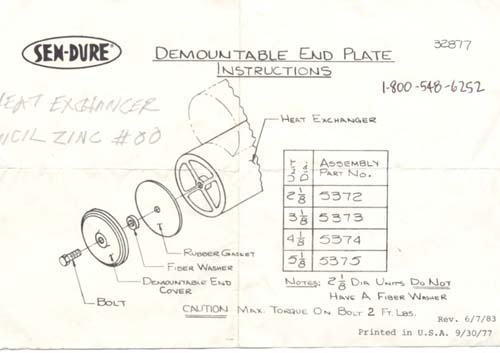
Diagram and instructions from Sendure. One of the sources for new end caps and gaskets.
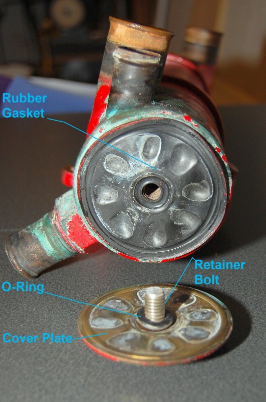
Picture of HX, partial disassembly of end cap.
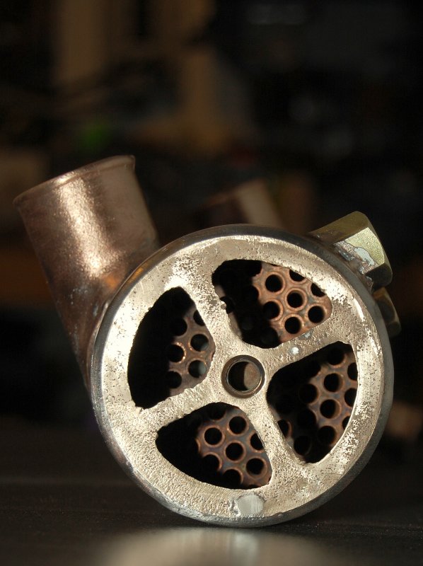
Picture of inside of HX. This is the pencil zinc end, it screws into the hex shaped fitting at the 1 o'clock position. When installed it fit in the cavity before the small cooling tubes start.
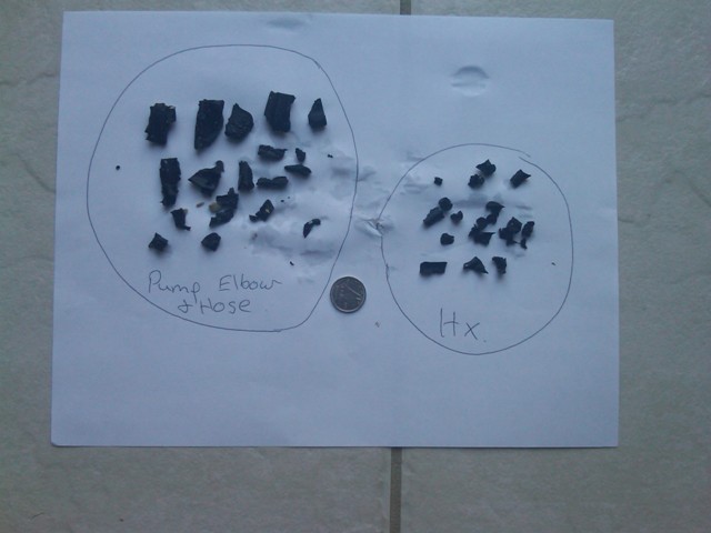
Picture of destroyed impeller bits taken from pump output and heat exchanger.
Picture Credits: I did not take any of these pictures, they were copied from posts on the forum. Thank you to the contributers.


