1987 MK 1 Catalina 34 Hanging Locker Storage
By Jon Windt; Della Jean
NOTE - Before doing any projects, I highly recommend that you first go through the “Critical Upgrades” list and verify that your boat has all of the applicable items addressed. There is a link on the Message Board (copied here) entitled “CRITICAL UPGRADES – DO THESE OR ELSE!!!” that will take you to them. It is a good way to both learn your boat and make sure it is safe. Don’t put it off.
Contents
Hanging Locker Storage
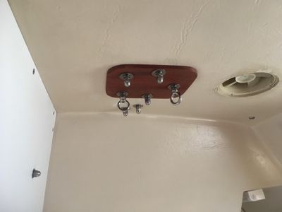
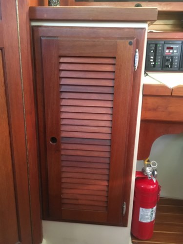
I purchased my 1987 MK 1 Catalina 34, hull #493 in April 2015. There aren’t many places to put food and drinks on the 1987 MK1 boat, and the ones that do exist require removing cushions or covers. Since I don’t use the hanging/wet locker just aft of the Navigation Station as either, I decided it was a good candidate to use for additional storage. I don’t use it as a hanging/wet locker because there isn’t a drain for the water that would accumulate in the bottom to get to the bilge. Instead I added a couple ring nuts to the winch bolts in the head as the hanging/wet locker as shown in photo (1).
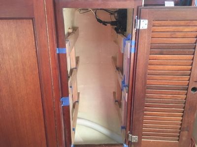
I decided this is a good choice because there is a lot of space inside, but without shelves or drawers it isn’t very useful as storage. Piling stuff up and closing the door isn’t very effective storage, especially when you want to get something out of there. The purpose of this project is to add sliding drawers plus a top shelf in the hanging/wet locker to provide for more storage that is convenient to use.
The Design Goals
- Add drawers in the hanging locker for food and drinks, screws, shackles, chargers, batteries, spare winch handles, etc..
- Drawers to visually match the rest of the cabinetry inside of the boat as best as possible.
- All drawers to be easily removable for access inside the locker, and to be able to return it back to an empty locker if needed/desired in the future.
Materials Used
- 3/4” Ash board rails for drawer slide supports and drawer faces, various lengths.
- Two 2 x 3’s to attach the horizontal drawer slide support rails to, 8 feet long.
- Two construction pine boards for drawer slide support rail mock-up, 1” x 6” x 8 feet.
- Two premium select pine boards for the drawer sides and ends, 1” x 6” x 8 feet.
- One premium select pine boards for the drawer sides and ends, 1” x 6” x 6 feet.
- Two 1/2” sanded both sides plywood for drawer bottoms and top shelf, 24” x 48”.
- ¼”sanded plywood remnants for drawer dividers.
- One 24” x 30” x 3/16” foam board.
- One Blum 22” standard drawer slide, 75 pound load capacity.
- Two Blum 26” standard drawer slide, 75 pound load capacity.
- Four IVES 3” brass slide bolts.
- #6 SST flat head screws, 1 1/2” long.
- #8 SST flat head screws, 1 1/2” long.
- #8 SST flat head screws, 2” long.
- West Systems SIX10 thickened epoxy adhesive.
- General Finishes Honey Maple oil based stain.
- DAP Plastic Wood, Golden Oak color.
- KILZ primer sealer
- Interior/exterior semi gloss latex white paint.
Making the Sliding Rail Supports
To have sliding drawers, you need a means to attach the rails to the interior walls of the locker. To meet the design goal of having a robust structure that’s easily removable back to original, I decided on using 2” x 3” studs mounted vertically with three dados cut into them for the horizontal drawer slide support rails to sit in. To attach the studs to the locker walls, they will be bonded in place with West Systems SIX10 thickened epoxy adhesive. To apply pressure to the studs during the bonding process, two #8 SST flat head Phillips screws will be used per stud.
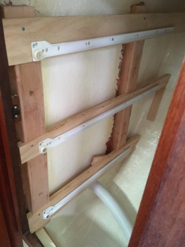
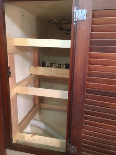
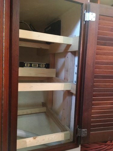
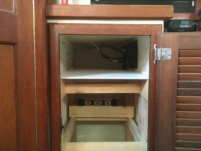
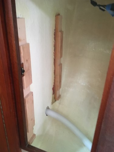
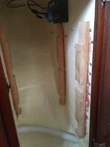
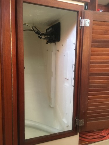
Photo (2) shows the 2” x 3” vertical studs with three dados cut into each one. Each one is held in place with only the two #8 SST screws at this time. Since this is the mock up phase, no epoxy adhesive is being used. Also installed are construction pine mock ups of the rail supports for the drawer slides to check for proper length and that they’re level from side to side. The fiberglass is not flat, or vertical so there’s lots of trial and error at this point which is why I am using construction pine instead of the more expensive Ash.
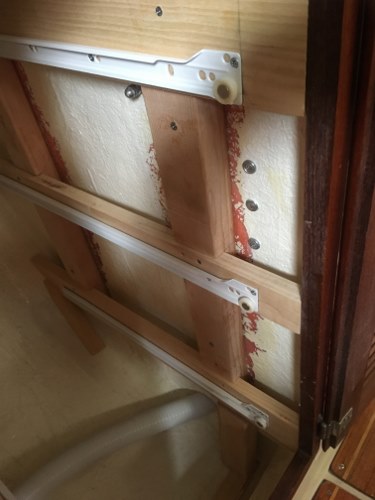
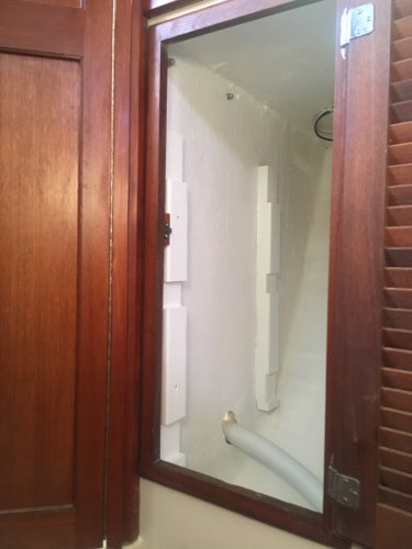
Photo (3) shows a closer view of the left side 2” x 3” vertical rail support. Photo (4) shows the right side 2” x 3” vertical rail support and how its’ placement has to take the screws for the Navigation Desk corbel into account.
The distance between the left and right side rails is to be 12 ¼”. This is the maximum width to make sure the drawers will slide in and out of the locker without interference with the louvered door trim. For the drawers to slide smoothly, it is critical to make sure the 12 ¼” distance is held constant for the length of each rail. To check this I used pieces of pine cut into 12 ¼” lengths with a spirit level and the digital level on my mobile phone as “go/no go” gauges. See photos (5) and (6).
Photo (7) shows the addition of the foam board mock up of the top shelf.
Final Fit Up
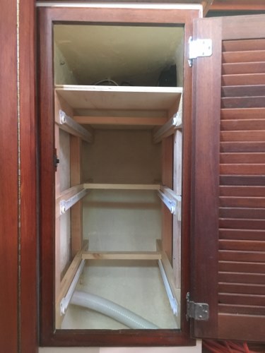
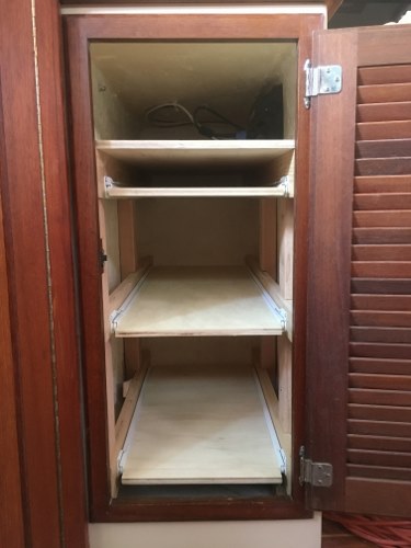
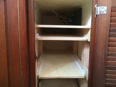
The 2” x 3” vertical rail supports, and horizontal pine drawer slide supports are in the proper 12 ¼” distance apart, square, and level side to side. The bottom and top rails are each 3” wide. The top rail is 3” wide to support the top shelf and be able have an ~2 5/8” drawer below it. The bottom rail is 3” wide to allow the Blum drawer slide to be as low as possible, and have enough material above it to install an IVES brass slide stop so the drawer doesn’t accidentally open while underway. The middle rail is 2” wide. The horizontal pine drawer slide supports can now be used to make the ash rail supports. Photo (8) shows the Ash rails installed, level, correct side to side distance with the Blum drawer slides, and the top shelf installed.
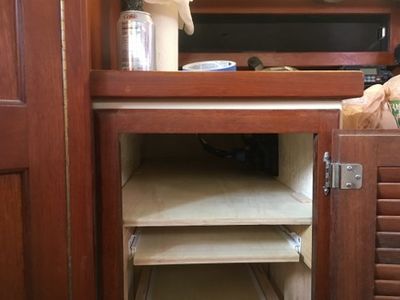
Photo (9) shows the drawer bottoms installed onto the Blum standard drawer slides to check for fit and smooth opening.
Photos (10) and (11) show close ups of the lower, middle, and upper drawer bottoms installed onto the Blum standard drawer slides.
Photo (12) shows the ¼” plywood top shelf and how the sides are notched so it can slip over the top of the 2” x 3” vertical rail supports. This ensures the top shelf will be removable if needed when the 2 x 3 vertical rail supports are epoxied to the walls of the locker.
Bonding The Supports
With all fit checks done, I sanded away the paint on the interior locker walls where the 2” x 3” vertical studs will be bonded to bare fiberglass. I then wiped with acetone and applied West Systems SIX10 thickened epoxy to the wall and the 2” x 3” vertical rail supports. To apply pressure while the epoxy cured I attached each one to the wall with two #8 flathead SST screws. I re-installed the Ash drawer slide supports to make sure all was square, and level side to side and fore and aft. To avoid anything slipping out of position while the epoxy cured, I added wood to shim at the base of the inboard vertical 2” x 3”vertical rail support and between the hull and Ash horizontal drawer slide supports on each side. See photos (13) and (14).
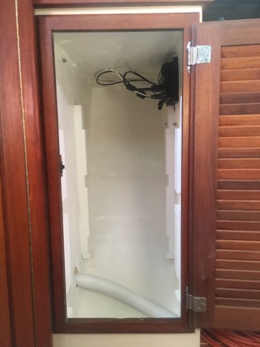
Photos (15) and (16) show the vertical 2 x 3’s bonded to the walls with the Ash horizontal drawer slide supports removed.
Painting The Supports
With the 2” x 3” vertical rail supports bonded to the walls, the next step is to put a coat of protective paint on the inside surface of the locker. These aren’t surfaces that will get wet very often, nor see much wear and tear so instead of using an expensive marine paint I used KILZ primer sealer and some interior exterior white paint I had in the garage. See photos (17), (18) and (19).
The Drawers
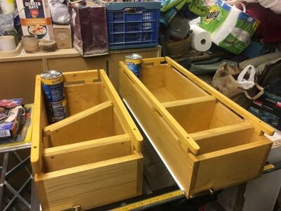
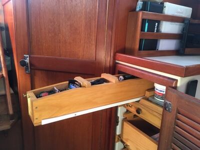
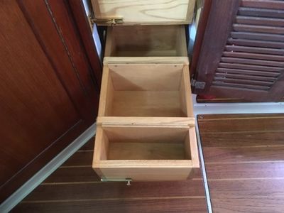
The drawers are built with premium select pine for the sides and back, ½” sanded plywood for the bottom, and ash for the front. The construction was a simple cut to size and screw together with #6 flathead Phillips SST screws, then stained with General Finishers Honey Maple Oil Based Wood Stain. I did not use any glue. The width dimension for the lower, middle, and upper drawers is 11 1/4” each. The bottom drawer is 22” long and 6” high. The middle drawer is 30” long and 6” high. The upper drawer is 33” long, but only 2 3/4” high. The very top drawer is 33” long, 4 ¾” wide, and 3 ¾” high. These are all outside dimensions. There wasn’t enough room to install another drawer to the right of the very top drawer, so I put a fiddle the shelf that matches the salon cabinet faces I installed on another project. This is where I’ll put the spare fuses, AAA, AA batteries, tape measure, etc.
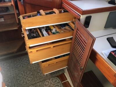
I added guard rails to the bottom and middle drawers to increase height a couple inches to better secure the contents in the drawers. (See Photo 20). The bottom drawer can hold/stack items with a maximum height of 10” without hitting the underside of the middle drawer. The middle drawer can hold/stack items with a maximum height of 8 ¾” without hitting the underside of the upper drawer. The top drawer can hold/stack items with a maximum height of 2 1/8” without hitting the underside of the upper shelf.
To keep the drawers from accidentally opening while underway I used IVES 3” brass slide bolts.
FYI – I do not use the brass screws that come with brass components. When screwing into Ash (or I suspect any hardwood) the head shears off and ruins your day. I use SST screws instead.
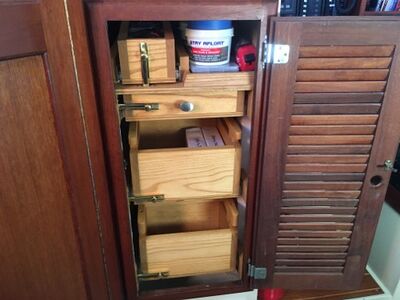
Photo (21) shows all of the finished drawers installed with a slide bolt for each. The upper drawer is so close to the top shelf, that it can’t be opened by pulling on the drawer front like the others, so I installed a knob to open it.
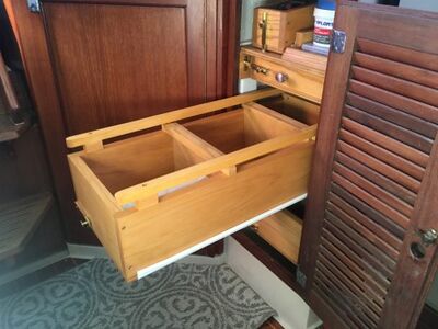
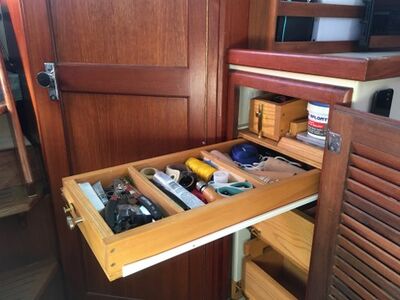
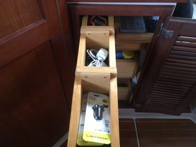
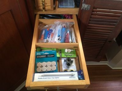
Photos (22), (23), and (24) show the finished bottom, middle, and upper drawers opened for reference. I put my two spare winch handles in the drawer in photo (24).
Photo (25) shows the top drawer that’s mounted to the shelf. To the right of the drawer you can see the fiddle. Farther back is a piece of wood as a backstop so nothing gets pushed back out of reach, and more importantly nothing accidentally hits the chart plotter.
Photo (26) shows a side view with all of the drawers open. You can see the Blum drawer slides I used. They attach to the bottom of the drawers instead of the sides. I wanted this type because I wanted the drawer slide to carry the load in the drawers, not the few screws attaching the bottom of the drawers.
Drawer Dividers
To keep things in each drawer from moving around while underway, I made dividers out of the remaining 1/2” plywood and Ash. Until I get a better idea of what will be stored in each drawer, I’m not going to screw the dividers in one place. If I decide to fix them in one position, I’ll do that by screwing the top of the divider to the sides of the drawer. Photo (27) shows the various pieces that make up the dividers after being stained to seal them.
(27)
The following photo’s are to provide a reference for how the dividers are intended to be installed. Photo (28) shows the two dividers placed into the top drawer, photo (29) shows the two dividers placed into the upper drawer, and photo (30) shows the two dividers placed into both the lower and middle drawers.
Completed Hanging Locker Storage
That’s it for this project.
PDF of This Write-Up
I've attached a copy of this complete write-up in a PDF format for reference. All links have been removed from the PDF.
File:1987 MK 1 Catalina 34 Hanging Locker Storage 01-17-19.pdf
