1987 MK 1 Catalina 34 Dual Tank Propane Locker
NOTE - Before doing any projects, I highly recommend that you first go through the “Critical Upgrades” list and verify that your boat has all of the applicable items addressed. There is a link on the Message Board (copied here) entitled “CRITICAL UPGRADES – DO THESE OR ELSE!!!” that will take you to them. It is a good way to both learn your boat and make sure it is safe.
Contents
Original Propane System Description
I purchased my Catalina 34 in April 2015. She is a 1987 MK1, hull #493.
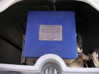
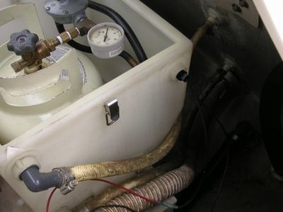
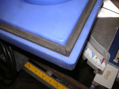
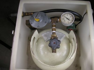
My original propane system consisted of a single 4# (~ 1 gal) steel tank mounted in a vented Seward brand locker ~ 13” x 13” x 12 1/4” that provided propane to the galley stove only. It was the typical white plastic and blue top with upper and lower ¾” vent bosses and integral mounting feet (which were cracked) molded into it. The top was closed tight by 4 SST latches and a foam gasket. It contained the tank, a regulator and gauge connected directly to the tank, a solenoid activated by a 5 Amp circuit breaker on the Main Distribution Panel, two short hoses connecting everything together.
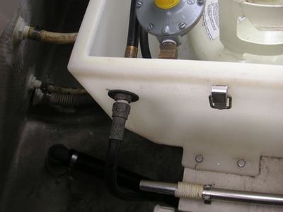
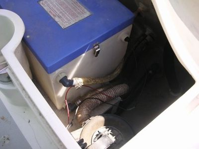
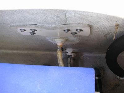
The locker was mounted on the wood cover above the steering radial inside the aft lazarette. The propane hose from the galley stove connected to the locker via externally threaded bulkhead fittings. The solenoid wires exited the locker through a hole drilled into a plastic fitting with silicone used as the sealant around the wires. Two ¾” male thread/hose barb elbows connected the locker upper and lower vents to two thru hulls in the transom with ¾” hoses.
Background
I am refitting my C34 for future short and extended cruising. I will use propane for the galley stove, and the small Magma grill I have mounted on the stern rail. Some questions I need to answer are should I have a tank and several disposable 1# bottles? What size tank? Where do I store the bottles? Are disposable 1# bottles the best way to provide propane to the grill?
For tank sizing, Don Casey’s rule of thumb is that 1# of propane will last 1 person 1 week cooking three meals a day.
After several iterations I decided to use an 11# low profile tank for the galley and add a 5# propane tank dedicated to the grill. I chose to use powder coated steel propane tanks manufactured by Manchester. I went with powder coated steel instead of aluminum because I couldn’t find a low profile (short) 10 or 11# aluminum tank, the powder coated steel tanks are much cheaper. I have strength concerns with the neck area on the fiberglass propane tanks so did not consider them at all.
FYI: My original tank was powder coated steel, and after 30 years in the sealed propane locker it still looked fine, so expect these to last at least as long as their certification.
This write up provides a summary of the propane system upgrade I did with photos, plus a parts list. I've numbered the photos to help with connecting the text to the associated photo.
This was not a very complicated project. The most difficult step was matching the hull mating surface of the support structures to the hull. There was lots of trial and error. As a final note, every boat is different. The routing, methods, and hose lengths I used may not work on your boat. Good luck and I hope you find this write up helpful.
Before Photos
The following photos show the boat before the propane system upgrade to help give you a perspective of my starting point. The text description for each group of photos is above them.
Photo (1) is the original propane locker mounted on the wood cover above the steering radial. It provides great access to the tank, gauge, and regulator. Being in the center of the lazarette opening blocks access for additional storage space. Photo (2) shows the externally threaded bulkhead fitting on the starboard side of the propane locker that the hose to the galley stove connects to.
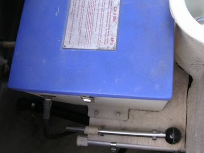
Photo (3) shows a crack in the mounting foot of the locker, and you can see one of the four SST latches used to clamp the top to the locker. Also shown are the Manual Bilge Pump and Emergency Rudder Handles mounted to the top of the wood radial cover. These will be relocated to the aft vertical 2 x 6 when the locker is relocated in the new design. Photo (4) shows the upper and lower ¾” vent elbows and hoses.
Photo (5) shows the vent hoses from the propane locker connecting to individual thru hulls in the transom. Photo (6) shows the solenoid wires exiting the locker through a hole drilled into a plastic fitting. Silicone was used to seal around the wires.
Photo (7) shows the gasket on the underside of the propane locker top. Photo (8) shows the inside of the original propane locker. The propane tank is original to 1987 so no OPD valve and no way to refill it. Lots of threaded connections and there was always a propane smell inside the locker.
Photo (9) shows the propane hose from the locker connecting to the back of the galley stove.
The Design Goals
- Relocate the propane locker away from the center of the aft lazarette so the large space between the transom and the aft water tank on a MK 1 can be take advantage of for storage, access to the manual bilge pump, and access to the steering radial.
- Install an 11# low profile propane tank for the galley stove, and a separate 5# propane tank for the stern rail mounted Magma grill in the same vented propane locker.
- Design and build a dual propane tank locker that is gas tight and vents overboard per code.
Where To Install?
The port side of the lazarette would not work because the manual bilge pump and hoses are located there. On many MK1’s, the refrigerator compressor is mounted to the hull on the starboard side. In my case the refrigerator compressor is mounted under the starboard salon seat in the main cabin so the starboard side of the aft lazarette was clear except for the Rule 1500 bilge pump hose that attaches to a thru hull near the chain plate up high on the transom. The bilge hose was far enough outboard, so I chose to install the new dual tank propane locker on the starboard side of the aft lazarette. The locker opening will be as close to the opening of the aft lazarette as possible to make removing and replacing propane tanks easier.
Propane Locker Mock Up
I decided where it will be installed, but still needed to answer:
- What length, width, or height to make this new propane locker?
- How to best orient the tanks inside the locker?
- How to make the top so it could be easily opened and capture the propane tanks so they would not rattle or move around while underway?
The height was limited to ensure a proper downward vent, and be able to remove and replace the 11# low profile propane tank which is ~ 12 ½” tall and ~12 1/4” in diameter at its’ widest point.
The length was limited to ensure the locker could be installed in one piece through the lazarette opening, once in the lazarette fit between the forward lazarette bulkhead and the angled transom, and be able to open the top of the propane locker so I could remove and replace the propane tanks when they needed to be refilled.
The width was limited to ensure the assembled propane locker could be installed through the aft lazarette opening and slide it into place in one piece.
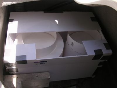
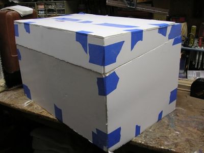
Too many opportunities for error, so I made a mock up. I used foam board for the locker and support structure, and I used heavy construction paper to make both propane tanks. Photo (10) shows one of the many mock up versions of the locker with tanks installed.
Photo (11) shows the mock up installed when looking down into the center of the aft lazarette from the cockpit. You can see the radial cover, the tiller cap, and part of the manual bilge pump for reference.
Photo (12) shows the final mock up with the mating surface between the top and the bottom changed to an angled surface. This change made it easier to remove both the top of the propane locker, and the propane tanks when it’s finally installed in the aft lazarrette.
Support Structure
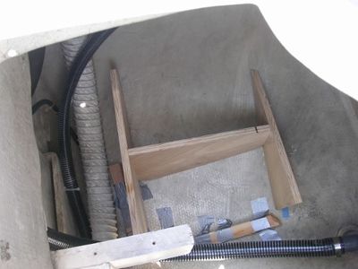
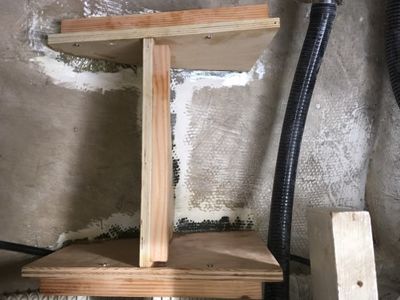
The length x width x height dimensions are now defined. I can now make the support structure from the mock up. For that I used ¾” plywood made into an “H” section. When the propane tanks are in the propane locker, they will be supported by the vertical legs. This will better carry the load directly to the hull. Photo (13) shows the dry test fit of the support structure before being epoxied and fiberglassed to the hull. The wood “L” shape that’s duct taped to the hull is helping to hold the structure in place. (not enough hands). The cockpit drain, 3” air vent, and bilge hose can also be seen in this photo.
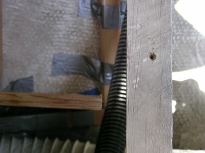
Photo (14) shows a close up of the clearance gap between the vertical leg and the starboard cockpit drain.
After matching the support structure surface to the hull surface it was time to epoxy the structure into place. I first marked the hull where the structure would be attached, then sanded the hull to remove the coating on the hull. I sanded a large enough area to have raw fiberglass where the structure would be epoxied directly to the hull, plus room for the fiberglass cloth I will also be using to bond the structure to the hull.
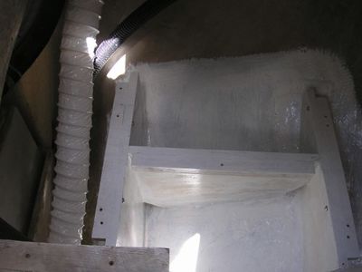
To epoxy the structure I used West Systems 610 thickened epoxy adhesive. The fiberglass I used West Systems 105 Resin, 205 hardener, and medium-density (6oz.) fiberglass cloth cut into 4” strips. Photo (15) shows the support structure after being epoxied in place. The support structure also now has stringers epoxied and screwed in place along the top edge. These are for the shelf, and the propane locker to attach directly with thru bolts to the support structure.
Photo (16) shows the support structure after being epoxied, glassed, and painted. The holes drilled in the stringers are for the shelf and propane locker attaching screws.
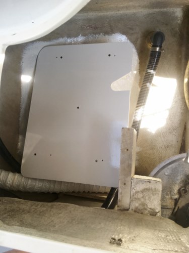
Photo (17) shows the new shelf the locker will sit on installed onto the support structure. The shelf is ½” plywood primed and painted with Interlux Brightside primer and topcoat white paint. It is attached with #10-32 flat head SST machine screws with SST flat washers and SST nyloc nuts on the underside.
Propane Locker
Using the mock up as the template, I made the locker using the glue and screw method with wood glue and #6 x 5/8” flat head SST wood screws. The general materials are as follows:
Bottom - The materials for the locker bottom assembly are:
- .25” plywood (which is .20” not .25”) for the sides, and bottom.
- 1x1’s used as stringers to attach the plywood surfaces together.
- A 2x4 to make the solenoid support, propane hose support.
- 1x5’s to increase the thickness along the top edge.
- .375” flat moulding for a sealing surface.
Once the locker was made I increased the vertical thickness along the top edge of the locker to ~ .70” using the 1x5 cut into pieces of 1.50”wide x .50” thick. The purpose for the increased thickness was to give the SST screws that will fasten the latches to the locker more solid wood material to bite into, to provide more surface for the .375” moulding to attach to, and to provide a surface for the vertical flange pieces in the propane locker top to seal against.
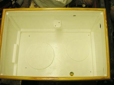
Photo (18) is the completed bottom of the locker and you can see:
- The 1x1 stringers, the solenoid support bracket (with two diagonal holes), and the hole for the vapor tight seal for the wires next to it.
- In the lower left is the propane hose support to protect against the weight of the regulator attached to the tank causing the POL fitting to come loose. (may be unnecessary).
- On the bottom are two .25” plywood discs to hold the propane tank bottoms in place.
- Along the upper side area is where I increased the thickness.
- The unpainted wood is the .375” thick moulding. I used polyurethane as a sealant instead of painting thinking it would provide a better, more durable sealing surface than paint.
- The hole in the bottom is for the .75” vent overboard. The two holes on the right side are for the vapor tight fittings to seal around the propane hoses as they enter the locker.
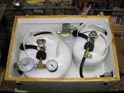
Photo (19) is a similar view showing the completed locker bottom with both tanks, on/off solenoid, regulator, gauge, hoses, and vapor tight seals installed. It’s hard to see, but there is a drip loop in the wires from the solenoid to the vapor tight seal.
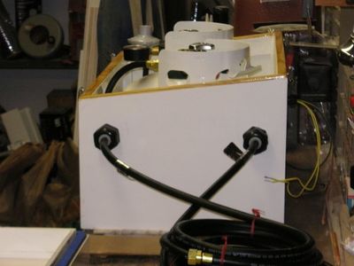
Photo (20) is an end view of the completed locker bottom with the tanks and components installed showing the vapor tight seals, propane hoses, and electrical wires from the solenoid.
Top - The materials for the top are:
- .25” plywood (which is .20” not .25”) for the top surface and internal “guards” for lack of a better term.
- The sides of the top are made from 1 x 5 clear pine cut to dimensions to match the mock up.
- .75” plywood to capture the tank tops so they don’t move or rotate when installed.
Photo (21) is the completed top of the locker and you can see:
- The .25” plywood (which is .20” not .25”) flanges attached to all four sides. They stick up ~ .50” above the sealing surface. When the top is installed, these flanges will stick into the locker bottom and provide a snug fit against the area I thickened to .70”, and in effect create another seal between the sides of the bottom and the top. Plus they act as a guide to help put the top on correctly in the dark.
- The inner surface of the top are two .75” plywood discs that I hand routed the outer grooves to match the top of the propane tanks. With the tanks on the .25” rings attached to the locker bottom (see 3rd bullet above), these .75” discs will capture the top of the propane tanks to keep them from rattling and rotating. The center section is routed out for the OPD valve to have clearance when it is opened and the propane system is being used.
- The foam seal is from Seward and used on their commercial product. It has an adhesive back that you remove and press it into place. Where I cut the gasket I used crazy glue gel to bond the ends together to try and keep a continuous seal. It is attached to the unpainted wood sides I made from the 1x5 clear pine. I used polyurethane to seal the wood instead of painting thinking it would provide a better, more durable bonding surface than paint.
FYI: To ensure I had a good sealing surface, I put a 75W light inside the locker with the wire passing through one of the holes. I clamped the top to the bottom with two beam clamps, taped over the holes for the propane hoses and electrical wires. I then turned out all lights in the garage and looked for light shining between the wood surface and the foam gasket. No light visible along the sealing surface means a good seal.
