Windlass installation w/ bow roller MK 1
By Michael Shaner
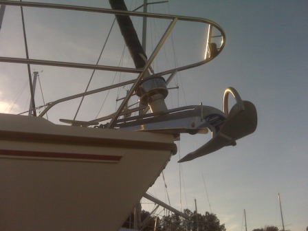
Following is a detailed summary of the installation of a Lewmar V1 windlass in combination with a new bow roller to accommodate a 35# Manson Supreme anchor.
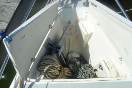
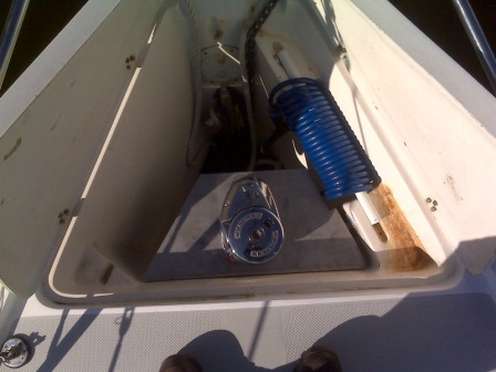
The anchor locker of a MK 1 is molded to accept two Danforth style anchors, apparently a “lunch hook” and a “big honkin’ one”. The dilemma was, there is no way to rapidly get the anchor overboard in case of emergency or to effectively manage the line. I don’t believe in lunch hooks and wanted to retain the “big honkin’ one” as a secondary anchor.
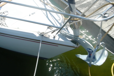
The MK 1 “toy” bow roller with new Manson Supreme.
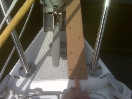
Bow roller template made to determine the mounting location taking into consideration the existing cleat, bow pulpit, etc.
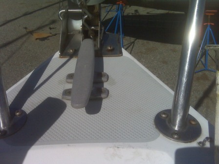
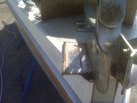
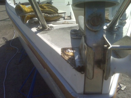
Remove the vertical portion of the existing roller. A 4 ½” grinder with a stainless cutting wheel does the job. Be careful of the heat generated by cutting so as not to “cook” the fiberglass. Cut an inch and douse with cool water. Wait 5 minutes. Repeat.
With the vertical portion gone, place the new bow roller in position. Trace the edge of the new roller on the remaining horizontal piece of the stem fitting to mark the next cut. Be careful not to cut the fiberglass under the existing fitting. Cut an inch and douse with cool water. Wait 5 minutes. Repeat…
Locate the mounting holes and drill. This would be a great location to oversize the holes, fill with epoxy and re-drill after cure. This is no place for moisture in the deck. If you can, tack weld the new roller to the existing stem fitting. Be sure to use a backing plate as the stress on the bow roller is HUGE.
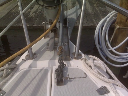
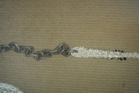
Rope / chain splice for smooth transition on the gypsy. I used 40 feet of ¼” G-4 high test chain spliced to 200 feet ½” 8 plait line. The V1 is available with a gypsy for 5/16” chain as well. Splice instructions available here [1]
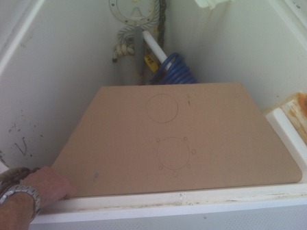
Templating the windlass platform.
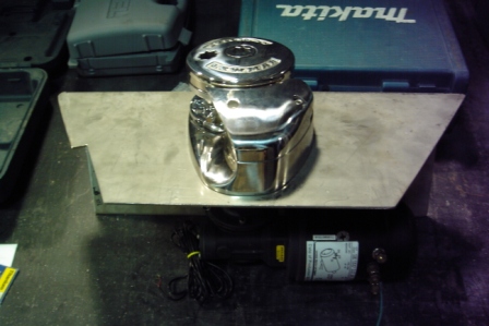
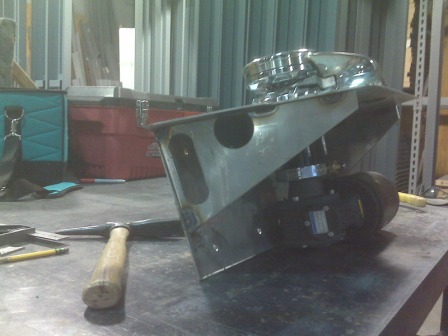
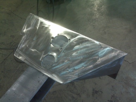
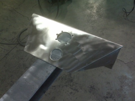
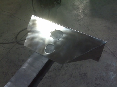
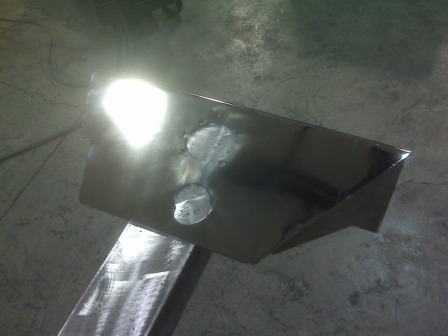
1/8” stainless steel plate cut and broken to match template. I used 304 stainless…316 would have been the better option. Most machine shops consider this amount of material “scrap”.
The “dry fit” to determine the wiring location, wash down pump outlet location, and assure the Danforth still fits…
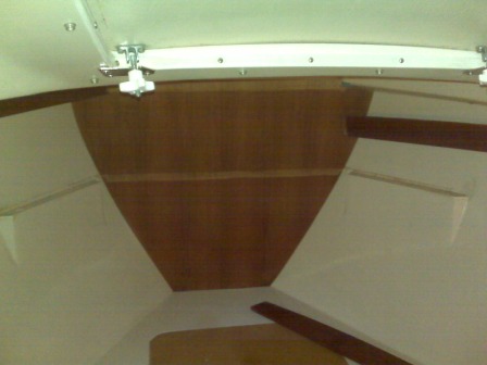
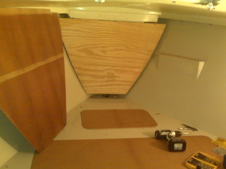
Parting out the V berth…
Locate and drill bracket mounting holes.
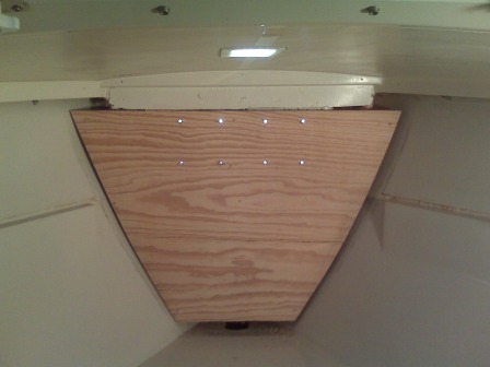
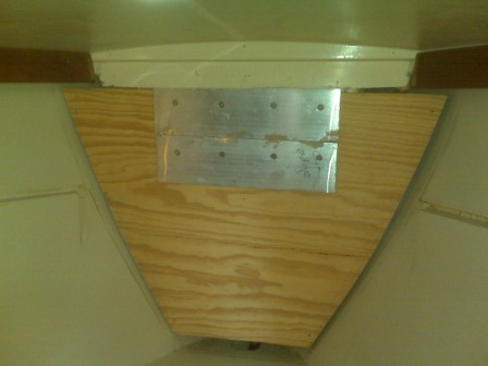
¼” thick aluminum backing plate with countersunk holes to accommodate 8 ea. countersunk head 5/16” stainless fasteners.
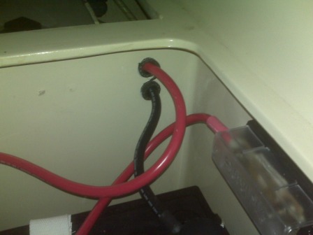
I powered the windlass from the house bank. For the length of the wire run (approx. 60 feet from batteries to contactor to windlass and back), Lewmar recommended #2 ga. cable. I drilled 7/8” OD holes and inserted ¾” ID reinforced hose at bulkhead / locker penetrations as chafe protection along the run. The chase goes from the house bank (typical location on MK 1), alongside stbd water tank to circuit breaker installed in forward setee. From circuit breaker to coaming behind stbd setee, through teak bulkhead into hanging locker. From hanging locker through bulkhead, chased underneath V berth along stbd side to contactor mounted to hull at forward end near anchor locker bulkhead. From contactor, behind anchor locker bulkhead (adjacent to anchor locker drain) to top stbd side of anchor locker, out to windlass motor.
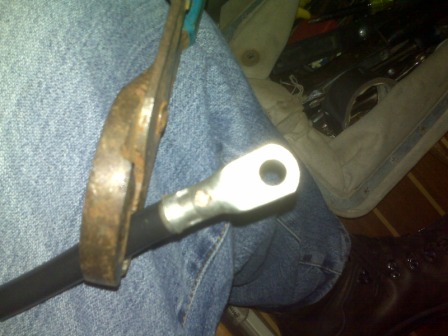
Somebody named Ron says “crimp for strength, solder for juice”. Crimp the cable to the connector, drill a 3/32 or so hole in the connector body, heat the connector with a soldering torch and fill with solder. Apply heat shrink tubing to seal the entire connection.
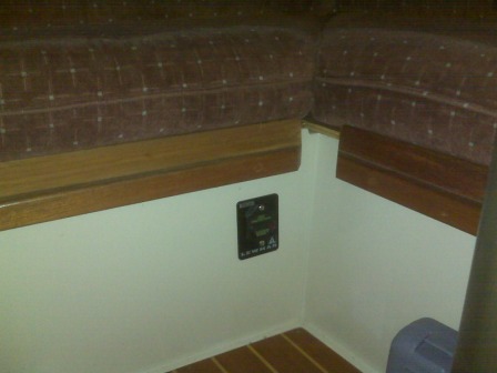
Lewmar supplied 90 amp circuit breaker located under the forward setee.
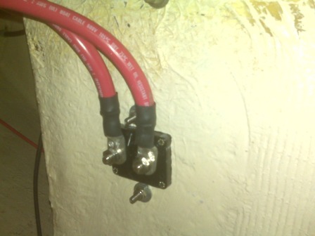
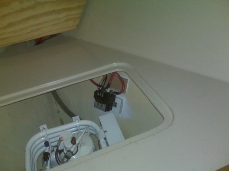
Contactor located under the V berth. I used a sealed oak block mounted to the hull with fast cure 5200.
Preliminary install…
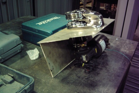
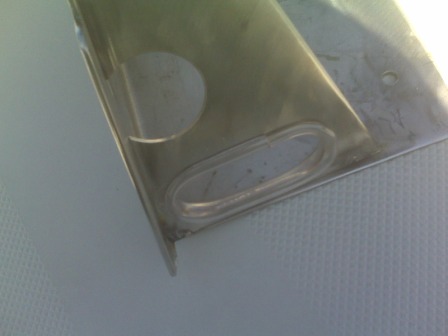
Gussets welded on. Access holes for wiring / wash down pump.
Polishing process…
Chafe protection for wiring…
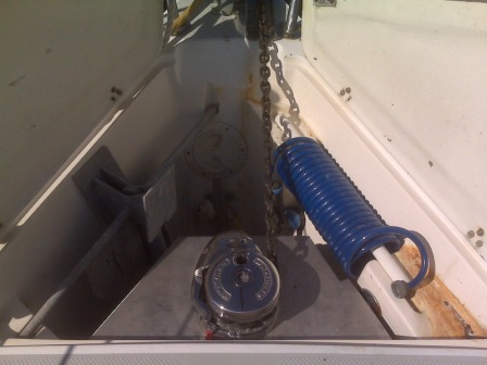
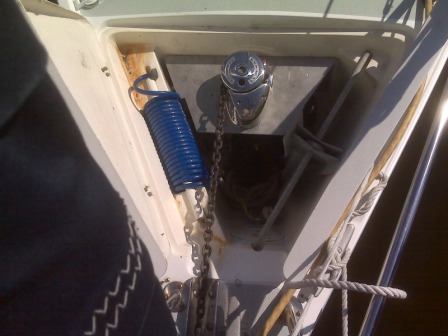
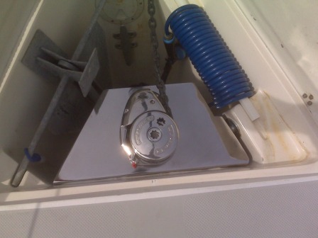
Final installation.
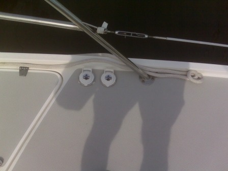
Deck mounted foot switches…this location worked nicely with the wire chase in the V berth. Another great location for the oversize/epoxy/re-drill and seal routine.
The windlass can be operated with only the stbd locker door open.
img...
