12 VDC Electrical System Upgrade – Winter 2003
By John Gardner, Seventh Heaven #695 (1988)
Among the many things I did during a busy winter in 2003 was an upgrade of the electrical system. During the inaugural trip of my 1988 boat, #695, at the end of last summer, we ran the fridge to make sure that repairs by the previous owner were effective. For most of the two hour trip we had to run the engine, and then a couple of miles from home, we dropped anchor for a cup of tea and cake (part of my English heritage). When we were ready to make the final leg to the mooring, the engine wouldn’t start, and you’re probably already ahead of me; the fridge had drained the batteries which were selected to “both.” I learned that leaving the system on “both” is a bad idea and that my electric system would not support the more comfortable sailing life that was supposed to come with the change from a Catalina 27 to a 34.
So I needed to upgrade the alternator, upgrade the battery bank, and improve the wiring.
Most of my sailing is weekend sailing in the Chesapeake, with the occasional trips up to a week or so. The boat is kept on a swinging mooring. With fridge, autopilot, nav equipment, radio, lights, and the desire for things like heated hair rollers (not me!), I concluded that my daily power usage could be as high as 100Ah per day. I concluded that despite limited use, the power demand and replenishment situations put me into the serious cruising category for power requirements. The batteries should be 400 Ah.
Contents
Alternator choice
I went round in the same circle many times deciding what alternator to get. I needed at least 75A, I wanted larger, but I was worried about the ability of the fan belt to transmit the power. Every place I looked or asked changed my mind. Suffice it to say that in the end I went with caution and obtained the 75A alternator. There was a little bit of black dust from the alternator belt, so I took a lot of care with alignment. I found that the alternator mounting bracket wouldn’t move quite far enough to give me the accuracy of alignment I wanted. So I removed it from the engine, slotted the holes slightly, and was able to get good alignment. I had the curved, under- the-alternator bracket, but the fan of the new alternator brushed against it. Using two screws I attached a piece of flat steel bar to extend the lower end of the bracket and hammered the ends of the screws over to ensure they couldn’t come undone.
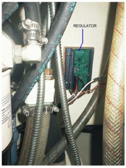
I epoxied a wood block to the wall at the back of the cupboard under the sink in the heads and attached the ARS-4 regulator to it. Connection was pretty straight forward following the Balmar instructions, although there was a little confusion because the color coding of the boat’s tachometer wire was not according to the diagram in the engine manual.
Battery box
Before installing the batteries I put in vents in the battery box under the seat forward of the sink. I put one near the floor at the starboard end of the forward facing wall of the seat base, and one up near the cushion in the end wall in the center of the boat.
With the benefit of hindsight I should have done that the other way round - the inboard one low, and the outboard one high, as that would have left more space for mounting other components in the battery box. The battery box is a double wall formed by the seat base on the outside and the battery box on the inside. I found that a sabre saw would just reach through the two layers and cut both at the same time. Working from the outside, the inside cut was a bit wobbly, but I ignored that. Grilles from West Marine finished the outside cutouts nicely.
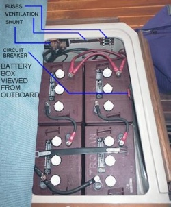
I put two blocks of 2 inch thick pressure treated wood in the pans at the bottom of the battery box. This made the base just about level. The 4 Trojan golf cart batteries are definitely a snug fit. These are 225 Ah each giving 450 Ah at 12V. There is about ½ inch between each battery, and also between the batteries and the aft wall. Space at the ends (port and starboard) is slightly better, and the forward space is irregular. I slipped ½ x 1 inch or similar pieces of wood into the gaps between the batteries and the walls to maintain what space there is, so that the batteries would have cooling air round them. I was uncertain how to hold them down, but this winter I will attach straps to the battery box walls and stretch them across the batteries in pairs.
In the battery box, as well as the Link shunt, I installed a switchable circuit breaker (50A) and a 4-fuse panel, both connected to the battery positive. The Link uses two of the fuses, the radio/CD player memory one fuse, leaving one spare. Because my new vent had removed a piece of wall, the circuit breaker had to be squeezed onto the forward wall of the box. It works, it’s not actually untidy, but it would have been better if everything had gone on the inboard wall.
Link 10 battery monitor
I mounted the Link 10 instrument in the wall of the hanging locker above the chart table hinge. I splurged and bought the manufacturer’s 4 pair cable to make the connections. The shunt for the Link is mounted in the battery box on the inboard wall above the batteries. The cable to it runs from inside the hanging locker, behind the electrical distribution panel, down into the holding tank area and through one of the ducts that crosses under the passage way. Thence up into the battery box. Connections all per the manufacturer’s diagrams. Despite the mess of two inch hoses in the end of the holding tank compartment, with a little patience and a bearable amount of frustration, I managed to push the thick cable through the duct. Once started it went fairly easily, and when the end was through, I added a tag line and pulled that through as well for future use.
Starting battery
As the golf cart batteries are deep cycle batteries, I reckoned they would not be very suitable for starting the engine except in an emergency. In any case I wanted shorter cables. The ‘old’ batteries of the boat (two different type 24s) were in fact starting batteries and appeared to be in good condition. The seller had claimed one of them to be new. I found that there was just room for a battery box under the access panel of the aft bunk. Ron Hill had pointed out that weight on the port side is a bad thing, so I installed it on the starboard side. I drew round the battery box on the hull to show where it would go. I cleaned the area with acetone and took off most of the finish (paint?) with a disc sander. With slips of wood I made a dam round the three lowest sides and held them in place with modeling clay, which also filled the gaps. Then I poured slow setting epoxy into the middle where it settled and solidified into a flat, level surface. After a few pourings I had raised the level surface just to the point where the surface was big enough for the battery box. (I nearly came to grief. I put in too much epoxy at one go. Of course it got hot while setting and nearly melted the modeling clay. Moral is, a little at a time.) Using screws, I attached strips of 3/4 inch aluminum angle to the edges of the new pedestal to locate the battery box, and epoxied blocks of wood to the hull fore and aft of the newly formed pedestal to receive screws to secure a battery box strap.
For the starting battery, the round trip to the starter is about 8 to10 ft of cable - a big improvement over the old circuit.
Wiring
Finally, cables. The circuit diagram shows the way everything is connected. In the original configuration, the cables were as follows:
Ground. Engine to battery box - #4 through heads sink cupboard and then in a fairly direct line under the sole to the battery box. Battery box to distribution panel - some small gauge wires through the ducts under the passage way, through the holding tank compartment and up to the distribution panel.
Positive. Starter to common of 1-2-Both switch - #4 under shower, hanging locker, and navigator’s foot space to the holding tank compartment, and then up behind the distribution panel. Battery 1 to 1-2-Both switch - #4 through the passage way ducts. Battery 2 to 1-2-Both switch - #4 through the passage way ducts.
I removed the positive wire at the 1-2-Both switch common terminal, and separated it from the loom back into the holding tank compartment. Then I pushed the end through the duct under the passage and threaded it up into the battery box. So now I have a #4 black and a #4 red from the engine compartment to the battery box. I also put in a #4 black cable from the battery box up to the electrical distribution panel area. That gave me two #4 red cables and one #4 black cable from the battery box to the distribution panel.
The distance from the alternator to the battery box is 13 ft. That comes to a round trip of 26 ft. With #4 wire that should provide no more than 3% voltage drop for current up to 40A. And from the batteries to the distribution panel, the distance is about the same, so again, 3% voltage drop at 40A. However, the loop there is the original #1 and #2 battery cables in one direction (i.e. 2 x #4), and a single ground cable (#4) for the return, so the ampacity is somewhat better than in the charging circuit. Of course there will still be losses out on the distribution wiring. Note that at present, master switch is either on or it is off; 1, 2 and both, all have the same effect, because they are linked at the battery bank.
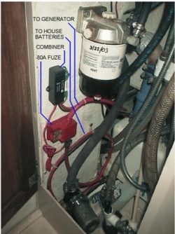
The positive cable from the house battery bank to the engine compartment is connected to the alternator via an 80A fuse that I installed under the heads sink. So the house batteries receive directly the benefit of the alternator charge. I have a combiner connected from the downstream side of the fuse to the starter battery. (Note that the combiner installation instructions warn not to cut the leads.). And finally, I installed a zap stop diode across the alternator terminals.
Sea ready
The system has been lightly used this season, but it seems to have done all that was required of it. The only further improvement I want to make is to add an isolation switch to the starter battery circuit. In fact I’d like to be able to isolate both battery banks from the cockpit, as a safety measure, but that almost inevitably involves solenoids. I am a bit reluctant to introduce these additional points of potential failure, so I will probably end up just adding either a solenoid or a direct switch in the starter circuit.


