Difference between revisions of "Cockpit Sole Inserts in Mahogany"
(design templates for a mahogany cockpit sole) |
|||
| Line 1: | Line 1: | ||
| − | Dan Harrington, Weal Sea #1289 | + | ==Detailed plans and step-by-step instructions for both the closed- and walk-thru transom Mk I models== |
| − | Ben Holland, ChriSea #832 | + | '''By Dan Harrington, ''Weal Sea'' #1289 and Ben Holland, ''ChriSea'' #832''' |
| − | |||
| − | The plans and instructions given here will allow most C-34 owners with access to a modest wood shop to make their own cockpit sole inserts. The cockpit sole we built is shown in Fig. A. | + | The plans and instructions given here will allow most C-34 Mk I owners with access to a modest wood shop to make their own cockpit sole inserts. The cockpit sole we built is shown in Fig. A.<br> |
| + | [[image:CockpitSole-A.jpg|border|700px|Finished cockpit sole]]<br> | ||
| − | |||
| + | The cockpit sole consists of a set of 4 inserts: (1) a bow section, (2) a stern section, (3) a starboard section and (4) a port section. Plans shown here are for both the "standard" and "walk-through" transom versions of the Mark I (pre-1995) C-34. The "bow section" is identical for both transom versions. (Fig. 1)<br> | ||
| − | 1. | + | [[image:CockpitSole-1.jpg|border|700px]] |
| + | ===Standard Transom:=== | ||
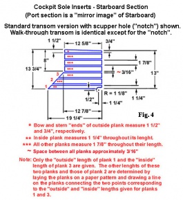
| + | The stern, starboard and port sections of the standard transom version have "notches" over the scuppers (drain) holes in the cockpit. In addition, a large notch is present in the back edge of the stern section to accommodate the "emergency tiller housing" in the transom that protrudes into the cockpit (Fig. 3A & Fig. 4). | ||
| − | 2 | + | <gallery caption="Click any image to enlarge" widths=325px heights=290px perrow=2> |
| + | image:CockpitSole-3A.jpg | ||
| + | image:CockpitSole-4.jpg | ||
| + | </gallery> | ||
| + | ===Walk-through Transom:=== | ||
| + | Two options for the walk-through transom version are show here. These differ only in the length of the stern section. The planking of the "short" type stern section stops at the slotted brackets that hold the plastic splash-board (Fig. A & 3B). The planking of the "long" type stern section extends all the way to the edge of the step down to the swim platform (Fig. 3C). | ||
| − | + | <gallery caption="Click any image to enlarge" widths=325px heights=220px perrow=2> | |
| + | image:CockpitSole-3C.jpg|Long section | ||
| + | image:CockpitSole-3B.jpg|Short section | ||
| + | </gallery> | ||
| + | |||
| + | ===Materials:=== | ||
We elected to use mahogany rather than teak because of cost and our preference for the appearance of mahogany. The sole "planks" were made from 3/8" thick mahogany. Almost all of the planking was made from 1 7/8" wide pieces. The exceptions were the 2 planks used on outside of the stern section that measured 2 5/8" in width. The "stringers" (cross pieces) were made from ¾" x 1 ¾" pieces of mahogany. The lengths varied, the longest being ~26"(stern section). | We elected to use mahogany rather than teak because of cost and our preference for the appearance of mahogany. The sole "planks" were made from 3/8" thick mahogany. Almost all of the planking was made from 1 7/8" wide pieces. The exceptions were the 2 planks used on outside of the stern section that measured 2 5/8" in width. The "stringers" (cross pieces) were made from ¾" x 1 ¾" pieces of mahogany. The lengths varied, the longest being ~26"(stern section). | ||
| − | Measurements & | + | ===Measurements & making patterns:=== |
The plans shown here were drawn using measurements that were made from the sections after they were assembled. While they are accurate, they should be used as a guide to make the paper and plywood "patterns" required to build the jigs for your particular boat (described below). | The plans shown here were drawn using measurements that were made from the sections after they were assembled. While they are accurate, they should be used as a guide to make the paper and plywood "patterns" required to build the jigs for your particular boat (described below). | ||
| − | Making paper patterns: | + | ====''Making paper patterns:''==== |
| + | #Using the "pattern" drawings shown in Fig. 5A - 5E, make a paper pattern of each of the sole sections from sheets heavy paper (e.g. heavy brown wrapping paper works well). | ||
| + | #Take the patterns to your boat and lay them out in the cockpit. Make any needed adjustments in the patterns to fit your cockpit. There should be a gap of at least ¼" between the bulkheads of the cockpit and the edges of the pattern. You do not want the sole sections to be too tight. | ||
| − | + | ====''Making plywood patterns:''==== | |
| − | |||
| − | |||
| + | You will use 1/8" plywood patterns to (1) double-check that the sole sections will fit in the cockpit, and (2) to make the "jigs" required to assemble the 4 sections. | ||
| + | #Using the "corrected" paper patterns, trace the pattern of each section onto a sheet of 1/8" plywood. Note that the starboard and port sole sections are mirror images of one another. Thus, only one pattern is required. | ||
| + | #Take your plywood patterns to the your boat and test fit. These plywood patterns are used to make the "jigs" used in assembling the sole sections. Therefore, be sure they fit exactly as you expect. You may even want to put "stringers" on the downside of the patterns for the test fit. | ||
| + | <gallery widths=350px heights=190px perrow=2> | ||
| + | image:CockpitSole-5A.jpg | ||
| + | image:CockpitSole-5B.jpg | ||
| + | image:CockpitSole-5C.jpg | ||
| + | image:CockpitSole-5D.jpg | ||
| + | image:CockpitSole-5E.jpg | ||
| + | </gallery> | ||
| + | ===Planking, Stringers & Spacers:=== | ||
| − | + | ====''Planking:''==== | |
| − | |||
| − | |||
| − | |||
| − | |||
| − | |||
| − | |||
| − | |||
| − | |||
| − | |||
| − | Planking: | ||
| − | |||
All planking was precut and their upper surfaces and edges sanded before assembling. It’s a good idea to start with the bow section since this section requires the longest planks (Fig. 2). Then, if you make an error in measuring or cutting, you can always use "shorter" planks for the stern or port / starboard sections. | All planking was precut and their upper surfaces and edges sanded before assembling. It’s a good idea to start with the bow section since this section requires the longest planks (Fig. 2). Then, if you make an error in measuring or cutting, you can always use "shorter" planks for the stern or port / starboard sections. | ||
| + | Using your plywood patterns, lay your stock planking on the patterns then mark and cut the planks. Be sure to number the downside of each plank to prevent a mix up during assembly. | ||
| − | + | [[image:CockpitSole-2.jpg|border|700px]] | |
| − | |||
| + | ====''Stringers:''==== | ||
Use the plywood patterns to cut the stringers in the same manner as described for the planking. The number and positioning of stringers (which need not be exact) is shown in Fig. 7A-7F. NOTE – Our stringers were ¾" thick, but ½" thick stringers would work just as well. | Use the plywood patterns to cut the stringers in the same manner as described for the planking. The number and positioning of stringers (which need not be exact) is shown in Fig. 7A-7F. NOTE – Our stringers were ¾" thick, but ½" thick stringers would work just as well. | ||
| + | <gallery widths=350px heights=190px perrow=2> | ||
| + | image:CockpitSole-7A.jpg | ||
| + | image:CockpitSole-7B.jpg | ||
| + | image:CockpitSole-7C.jpg | ||
| + | image:CockpitSole-7D.jpg | ||
| + | image:CockpitSole-7E.jpg | ||
| + | image:CockpitSole-7F.jpg | ||
| + | </gallery> | ||
| − | + | ====''Spacers:''==== | |
| − | |||
| − | |||
| − | |||
| − | Spacers: | ||
| − | |||
To keep the gap between the planks equal while the stringers are being attached during assembly, 3/16" scrap-wood "spacers" are inserted between the planks. Since spacers are removed and reused as each stringer is attached, you’ll only need to make about 30. | To keep the gap between the planks equal while the stringers are being attached during assembly, 3/16" scrap-wood "spacers" are inserted between the planks. Since spacers are removed and reused as each stringer is attached, you’ll only need to make about 30. | ||
| − | |||
| + | ===Assembly Jigs:=== | ||
Jigs are used to hold planks of the sole sections in place during assembly. A diagram of the jig used to assemble the Bow Section is shown in Fig. 6. This jig is made by laying your plywood "pattern" of the Bow Section on a 4’x8’ sheet of ½" plywood and then nailing 1" x ½" strips of scrap wood around the outside of the pattern to form an outline of the Bow Section insert. The pattern is removed and the planks are then inserted for assembly (described below). | Jigs are used to hold planks of the sole sections in place during assembly. A diagram of the jig used to assemble the Bow Section is shown in Fig. 6. This jig is made by laying your plywood "pattern" of the Bow Section on a 4’x8’ sheet of ½" plywood and then nailing 1" x ½" strips of scrap wood around the outside of the pattern to form an outline of the Bow Section insert. The pattern is removed and the planks are then inserted for assembly (described below). | ||
| + | [[image:CockpitSole-6.jpg|border|700px]] | ||
| − | Assembly & Finishing | + | ===Assembly & Finishing:=== |
| − | + | All sections of the cockpit sole inserts are assembled in jigs in the same manner. Thus, only the steps used to assemble the Bow Section are described here. Bow Section Insert: | |
| − | All sections of the cockpit sole inserts are assembled in jigs in the same manner. Thus, only the steps used to assemble the Bow Section are described here. | ||
| − | |||
| − | Bow Section Insert: | ||
| − | |||
| − | |||
| − | |||
| − | |||
| − | |||
| − | |||
| − | |||
| − | |||
| − | |||
| − | |||
| − | |||
| − | |||
| − | |||
| − | |||
| − | + | #Place precut numbered planks inside the assembly jig "finished side" down. | |
| + | #Using a tape measure and pencil, draw a line across the planks where each stringer is to be attached (Fig. 7A). | ||
| + | #Stringers are now attached starting at the "bow end" of the insert. To keep the gap between the planks equal while the stringers are being attached, wooden spacers are inserted between the planks. Two rows of 3/16" spacers are placed between the planks parallel to the "bow-end" of the jig. The first row should be about 6" from the bow-end of the jig. The second row should be 10"-12" from the bow-end of the jig. <div style="padding: 10px; border: 1px solid #FFAA99; font-family: Ariel, sans-serif">NOTE: Planks should lay "flat" inside the jig and "snug" against its sides without buckling. If the planks buckle, make and use a few additional spacers slightly thinner than 3/16". If the planks are not snug against the sides of the jig, make a few spacers slightly thicker than 3/ 16"… remember, the 3/16"gap between planks is approximate, not exact.</div> | ||
| + | #Put a spot of good quality waterproof glue on each plank between the penciled lines where the first stringer is to be attached. | ||
| + | #Staple the stringers in place using a power stapler. You can drill holes and add screws later if desired. We used staples only. | ||
| + | #Move the spacers to the next stringer location and repeat steps 4 and 5 above. | ||
| + | #When the glue has dried, use a router to cut several 1/4"-deep grooves in each stringer to permit water to drain to the scuppers or out the stern in boats with a walk-through transom (Fig. 7A and photo Fig. B) | ||
| + | #Lightly re-sand exposed surfaces and apply (spray preferred) 5 or 6 coats of good quality marine polyurethane or varnish. | ||
| + | #To prevent abrasion to the gel coat of the cockpit sole by the stringers, strips of self-adhesive felt pads are applied to the underside of the stringers (Fig. B). | ||
| − | |||
| − | + | [[image:CockpitSole-B.jpg|border|700px]] | |
Revision as of 17:23, 31 January 2009
Detailed plans and step-by-step instructions for both the closed- and walk-thru transom Mk I models
By Dan Harrington, Weal Sea #1289 and Ben Holland, ChriSea #832
The plans and instructions given here will allow most C-34 Mk I owners with access to a modest wood shop to make their own cockpit sole inserts. The cockpit sole we built is shown in Fig. A.

The cockpit sole consists of a set of 4 inserts: (1) a bow section, (2) a stern section, (3) a starboard section and (4) a port section. Plans shown here are for both the "standard" and "walk-through" transom versions of the Mark I (pre-1995) C-34. The "bow section" is identical for both transom versions. (Fig. 1)

Standard Transom:
The stern, starboard and port sections of the standard transom version have "notches" over the scuppers (drain) holes in the cockpit. In addition, a large notch is present in the back edge of the stern section to accommodate the "emergency tiller housing" in the transom that protrudes into the cockpit (Fig. 3A & Fig. 4).
- Click any image to enlarge


Walk-through Transom:
Two options for the walk-through transom version are show here. These differ only in the length of the stern section. The planking of the "short" type stern section stops at the slotted brackets that hold the plastic splash-board (Fig. A & 3B). The planking of the "long" type stern section extends all the way to the edge of the step down to the swim platform (Fig. 3C).
- Click any image to enlarge

Long section

Short section


Materials:
We elected to use mahogany rather than teak because of cost and our preference for the appearance of mahogany. The sole "planks" were made from 3/8" thick mahogany. Almost all of the planking was made from 1 7/8" wide pieces. The exceptions were the 2 planks used on outside of the stern section that measured 2 5/8" in width. The "stringers" (cross pieces) were made from ¾" x 1 ¾" pieces of mahogany. The lengths varied, the longest being ~26"(stern section).
Measurements & making patterns:
The plans shown here were drawn using measurements that were made from the sections after they were assembled. While they are accurate, they should be used as a guide to make the paper and plywood "patterns" required to build the jigs for your particular boat (described below).
Making paper patterns:
- Using the "pattern" drawings shown in Fig. 5A - 5E, make a paper pattern of each of the sole sections from sheets heavy paper (e.g. heavy brown wrapping paper works well).
- Take the patterns to your boat and lay them out in the cockpit. Make any needed adjustments in the patterns to fit your cockpit. There should be a gap of at least ¼" between the bulkheads of the cockpit and the edges of the pattern. You do not want the sole sections to be too tight.
Making plywood patterns:
You will use 1/8" plywood patterns to (1) double-check that the sole sections will fit in the cockpit, and (2) to make the "jigs" required to assemble the 4 sections.
- Using the "corrected" paper patterns, trace the pattern of each section onto a sheet of 1/8" plywood. Note that the starboard and port sole sections are mirror images of one another. Thus, only one pattern is required.
- Take your plywood patterns to the your boat and test fit. These plywood patterns are used to make the "jigs" used in assembling the sole sections. Therefore, be sure they fit exactly as you expect. You may even want to put "stringers" on the downside of the patterns for the test fit.


Planking, Stringers & Spacers:
Planking:
All planking was precut and their upper surfaces and edges sanded before assembling. It’s a good idea to start with the bow section since this section requires the longest planks (Fig. 2). Then, if you make an error in measuring or cutting, you can always use "shorter" planks for the stern or port / starboard sections.
Using your plywood patterns, lay your stock planking on the patterns then mark and cut the planks. Be sure to number the downside of each plank to prevent a mix up during assembly.

Stringers:
Use the plywood patterns to cut the stringers in the same manner as described for the planking. The number and positioning of stringers (which need not be exact) is shown in Fig. 7A-7F. NOTE – Our stringers were ¾" thick, but ½" thick stringers would work just as well.


Spacers:
To keep the gap between the planks equal while the stringers are being attached during assembly, 3/16" scrap-wood "spacers" are inserted between the planks. Since spacers are removed and reused as each stringer is attached, you’ll only need to make about 30.
Assembly Jigs:
Jigs are used to hold planks of the sole sections in place during assembly. A diagram of the jig used to assemble the Bow Section is shown in Fig. 6. This jig is made by laying your plywood "pattern" of the Bow Section on a 4’x8’ sheet of ½" plywood and then nailing 1" x ½" strips of scrap wood around the outside of the pattern to form an outline of the Bow Section insert. The pattern is removed and the planks are then inserted for assembly (described below).

Assembly & Finishing:
All sections of the cockpit sole inserts are assembled in jigs in the same manner. Thus, only the steps used to assemble the Bow Section are described here. Bow Section Insert:
- Place precut numbered planks inside the assembly jig "finished side" down.
- Using a tape measure and pencil, draw a line across the planks where each stringer is to be attached (Fig. 7A).
- Stringers are now attached starting at the "bow end" of the insert. To keep the gap between the planks equal while the stringers are being attached, wooden spacers are inserted between the planks. Two rows of 3/16" spacers are placed between the planks parallel to the "bow-end" of the jig. The first row should be about 6" from the bow-end of the jig. The second row should be 10"-12" from the bow-end of the jig. NOTE: Planks should lay "flat" inside the jig and "snug" against its sides without buckling. If the planks buckle, make and use a few additional spacers slightly thinner than 3/16". If the planks are not snug against the sides of the jig, make a few spacers slightly thicker than 3/ 16"… remember, the 3/16"gap between planks is approximate, not exact.
- Put a spot of good quality waterproof glue on each plank between the penciled lines where the first stringer is to be attached.
- Staple the stringers in place using a power stapler. You can drill holes and add screws later if desired. We used staples only.
- Move the spacers to the next stringer location and repeat steps 4 and 5 above.
- When the glue has dried, use a router to cut several 1/4"-deep grooves in each stringer to permit water to drain to the scuppers or out the stern in boats with a walk-through transom (Fig. 7A and photo Fig. B)
- Lightly re-sand exposed surfaces and apply (spray preferred) 5 or 6 coats of good quality marine polyurethane or varnish.
- To prevent abrasion to the gel coat of the cockpit sole by the stringers, strips of self-adhesive felt pads are applied to the underside of the stringers (Fig. B).
