1987 MK 1 Catalina 34 Electrical System Upgrade
By Jon Windt; s/v Della Jean
NOTE - Before doing any projects, go through the “Critical Upgrades” list and verify that your boat has all of the applicable items addressed. There is a link on the Message Board titled “CRITICAL UPGRADES – DO THESE OR ELSE!!!” that will take you to them. Don’t put it off.
Contents
General Vessel Description
I purchased my Catalina 34 in April 2015. She is a 1987 MK1, hull #493.
Mechanically she came with a M25XP 23 hp Universal (Kubota) 3 cylinder diesel, Hurth transmission, traditional packing gland, 3 blade 15x9 prop, keel stepped mast, Harken roller furling head sail, footed double reef main, standard rig with a fin keel, a standard rudder for 1987, a dodger with stainless steel tubing for the frame and hand holds over the companionway, and davits from Forespar for the 10’ 2” Walker Bay RIB dinghy/tender.
Electrically she came with 2 Group 24 105ah Trojan 12VDC batteries, a ProMariner Sport 20 AC battery charger, 12VDC refrigerator compressor, 1-2-Both battery switch mounted on the original OEM main distribution panel at the Navigation Station, 105A Leece-Neville (8MR2401UA) internally regulated alternator on the engine, a mix of LED and incandescent lighting throughout the cabin, IC-M422 ICOM VHF radio and a non-working Loran Navigation system both mounted at the Navigation Station, original engine control panel in the cockpit, non-working Autohelm ST3000 (1998 vintage wheel pilot), removable Command Mike with connection plug near the engine control panel in the cockpit, 5” display fish finder, removable GPS display and Tacktick at the helm.
Background
I am not an expert in marine electrical systems. I have been able to accomplish this upgrade only because of the breadth of documentation and the experts willing to share their knowledge and experiences that participate on the C34IA forum. I decided to write up my project as a way to pay back everyone that helped, and provide another reference for others wanting to do a similar upgrade to their boat. This is not a technical discussion on how things work. For that I recommend you read the Electrical Systems 101 in the Tech WIKI, and my posting 1987 MK1 Electrical System Upgrade – Feedback Requested for detailed discussion, graphs, and curves. This write up provides a complete summary of the electrical system upgrade I did with photos.
FYI - Before I hooked-up the batteries or turned anything on, I hired a marine electrician to inspect and approve my work, and the design, then sign & date the schematic for insurance.
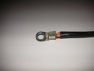
So why do such a complex electrical upgrade? Like a good new owner, I first did all the items in the “Critical Upgrade” list for my vintage boat. While doing the engine harness critical upgrade, I noticed an upgraded 105A alternator, but the system including the main cables had not been upgraded. The alternator output cables still ran through the starter then ~ 20 cable feet to the C post of the 1-2-Both battery switch instead of direct to the house bank, all cables in the charging circuit were 4AWG, the lug terminals were OEM automobile grade wrapped in black electrical tape that was falling off. No marine grade heat shrink tubing or heat shrink terminals were present. My charging system needed to be upgraded for both safety, and being able to cruise for long stretches of time.
FYI - I realized the importance of heat shrink tubing and heat shrink terminals doing the engine harness upgrade. When I removed the engine control panel in the cockpit, the ignition wire and blower motor wires fell out of their crimps. No tugging on anything, they just fell out. They were corroded and without heat shrink terminals. Imagine trouble shooting that out at sea!
For me this was a very complex project, remember I’m brand new to this. Depending on your level of experience, it may be quicker for you. In total the project took ~ 250 hours. I spent ~ 125 hours reading the Electrical Systems 101 topics, previous project write-ups, and started my own thread 1987 MK1 Electrical System Upgrade – Feedback Requested to ask questions on the C34IA website, then ~125 additional hours doing the actual work on the boat. Nothing was straight forward the first time around. It required lots of thought and decisions each step of the way. All in all, 85 DC and AC wires ranging in size from 16 AWG to 1 AWG have either been installed new, or the existing wires were re-routed, or re-terminated due to either corrosion, damage, making shorter runs, or to increase the number of separate grounds.
I checked everything as I went, whether or not it was part of the upgrade. Examples - Navigation Station desk bolts were about to fall off, 3 of 4 macerator motor mounting screws were loose, the heat shrink butt connector a Previous Owner installed on the new macerator motor was not heat shrunk, and the insulation on the motor positive wire had been worn away leaving a bare conductor. All bolts and screws are tight now, and the damaged wire replaced and heat shrunk.
As a final note, every boat is different. The routing and methods I used and wire/cable lengths may not work on your boat. Please read this as a guide of what I did, not as a manual of what you must do. This is one way, not the only way. Good luck and I hope you find this write up helpful.
Before Photos
The following photos show the boat before the electrical upgrade. The text description for each group of photos is above them. They are provided to help give you a picture of the starting point.
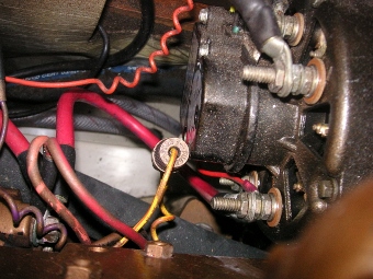
The left photo looks down at the original red 4 AWG cable from the 105A alternator output to the starter. The other red 4 AWG cable runs from the starter, ~ 20 cable feet to the 1-2-Both switch at the Navigation Station. The right photo is one example of a negative battery cable and lug with electrical tape removed. Notice the crimp terminal and the exposed wire end by the ring.
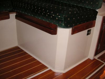
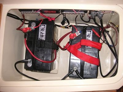
The photo on the left is the outside of the OEM battery compartment showing no ventilation openings. The switch in the upper right inboard side of the battery compartment is where the auto/on/off bilge pump switch was originally located. The photo on the right shows the original 2x Group 24 batteries, the 2 busbars, and a shunt for the Link 10 inside the battery compartment.
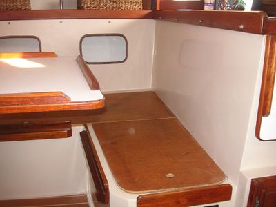
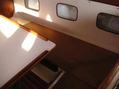
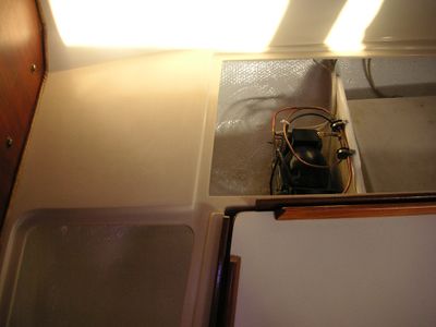
These 3 photos are of the traditional C34 salon area with all of the cushions removed. The black cover in the second photo is the existing ventilation cover for the DC refrigerator compressor.
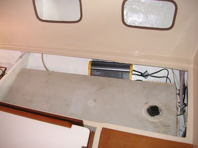
The first 2 photos show the salon area with the wood covers removed. You can see the fridge compressor on the left, and the water tank and 20A AC charger (which wasn’t fastened) in the center. The right photo shows the holding tank, macerator pump, hoses, and if you look close the original wiring and cables running up to the master distribution panel at the Navigation Station.
