C34 Exhaust with Water Cooled Riser
By Bill Shreeves
S/V Beginnings
Contents
Leading up to the Redesign / Replacement
On our 1987 C34, we inherited a Westerbeke 90-degree water injection elbow as part of the exhaust system that was installed when the boat was re-powered in 2005 by a previous owner. After research on this forum, I learned that the exhaust was not installed properly, no thanks to the surveyor and PO. So, I planned on "fixing" the exhaust during the next winter lay-up. Unfortunately, while cruising up the Delaware Bay under power to our new home marina at the beginning of our second season, the flange on the water-injection elbow failed. What follows is the redesign and replacement.
Exhaust system being replaced:
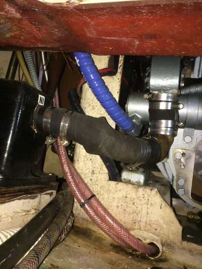
A Westerbeke 2” 90-degree water-injection elbow outlet was connected to a 1-5/8” 90-degree Centek elbow then connected to the starboard side of the 1-1/2” inlet to the Vernalift muffler. There was a very noticeable rise to the 1-1/2” muffler inlet (see photo 1). I don’t know why it was repowered in 2005 or why the exhaust system was changed in this way. I just knew it wasn’t correct and appeared to have a significant risk of water ingestion. Disassembly showed the water injection outlet to muffler inlet reductions were managed by doubling up on sections of hose. Needless to say, there was a greater risk for exhaust leakage than I realized as well. If/when I buy another used boat, I’ll pay very close attention to the exhaust. So much for depending on a surveyor to identify issues.
- NOTE: You may notice the absence of the gearbox in Pic 1. I used a photo taken during my gearbox replacement project a couple of months before the exhaust failure.
 Pic 1 - Looking FWD at pre-existing exhaust system
Going Forward:
I intended to simply install an exhaust system like originally installed on C34’s with materials purchased from Catalina Direct plus the upgrades available. Unfortunately, their Aqua Lift supplier was no more, with zero in stock and they were trying to locate a new supplier. They told me it could be several months before having one available so, I began my research on alternatives.
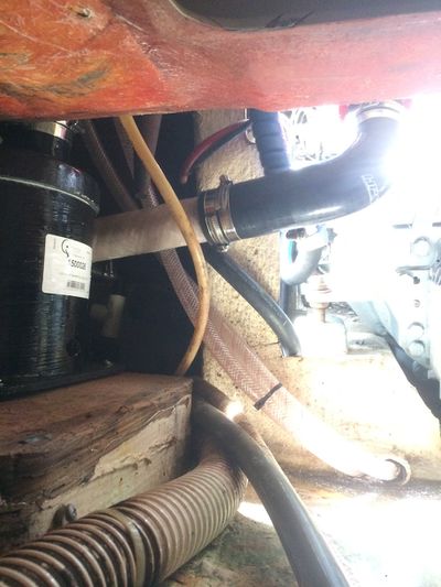
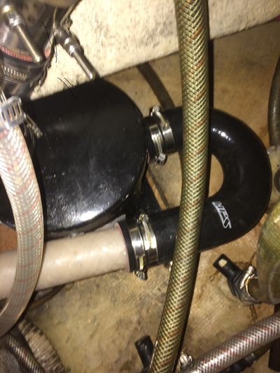
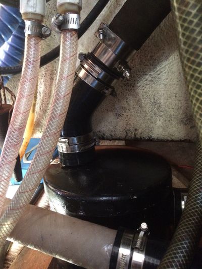
I reached out to this forum’s good friend Ken Kloeber with Weekend’R Products because I’d read on some forum posts that he had experience with replacing Catalina exhaust systems. I sent him pictures of the existing exhaust system and we had several long discussions on exhaust design. The most important factors for me were an improved design that was safe and reliable. I also preferred to stay with parts that I wouldn’t have to wait long for. After learning from Ken that Westerbeke makes a high-rise water injection elbow for this engine, I wanted to see if one could fit. Ken sent me a PDF of a full-size profile pic of the high-rise which I glued to a piece of cardboard to make a cut-out and took it down to the boat. Sure enough, with a little bit of trimming to the bottom of the bulkhead above the engine, to provide some “comfort” clearance, it would fit (See Pic 2). The next problem was my existing Vernalift rectangular muffler with 1-1/2” inlet and outlet. After some very careful measuring we decided to go with a new 8” round Vernalift muffler with 2” side inlet and 2” top outlet to avoid stepping down from the 2” high-rise outlet before entering the muffler plus, it was readily available. The 2” tube running in front of the muffler was a much tighter fit than planned due to a miscalculation (so much for very careful measuring – best laid schemed…) however, it did fit with just enough clearance to avoid wear from vibration (whew, See Pic 4). I made a few small adjustments after the pic was taken to provide a little more clearance.
The primary space constraints were the muffler top outlet projecting higher than the bottom of the cockpit port locker and the diameter of the muffler. The outlet height prohibited me from moving the muffler further aft to provide additional room for the horizontal 2” tubing in front of the muffler. With hindsight being 20/20, it would’ve been a better fit with a Vernalift rectangular muffler with 2” side inlet and 1-5/8” top outlet which will provide more room and avoid the need for the 2” to 1-5/8” reducer on the outlet I used. Ken says Centek will make this to order with little additional cost. With the rectangular muffler you’d have about an inch more room than I had with an 8” round for this configuration on the 34 MKI with a M25XPB. If the M35 is longer than the M25, you may not have enough to go in front of the muffler. If interested in keeping the inlet to port, an alternative might be to run the tube behind the muffler.
As of this post, I've run with this solution for half of a season. I've been very satisfied with it and I no longer have worries over water ingestion from the inherited exhaust system. As I wrote earlier, a rectangular Vernalift muffler with 2" side inlet and 1-5/8" top outlet would fit better and addressed my need for a reducer. FYI: As an additional step, to help reduce the volume of water that can run back to the muffler, I made sure that the high-point of the exhaust hose is as close to directly above the muffler in the port locker as possible.
Many, many thanks to Ken for all his help and patience in helping a newbie through this!
List of materials
· Westerbeke Wet Riser Kit 37403, includes v Clamp and gasket
· Centek 8x8 side in/top out Vernalift muffler
· Vernatube 2" x 20"
· Vernatube 2" - 1-5/8" reducer
· 2" Silicone 90-degree elbow
· 2" Silicone 45-degree elbow
· 2" Silicone 180-degree elbow
· (2) 2" T-bolt clamps
· (12) 2-1/2" ABA clamps
· Stainless or Brass 1/4" NPT pipe plug
· Stainless or Brass 3/4" NPT pipe plug
· Stainless or Brass 3/4" NPT x 5/8" hose barb
· Stainless grade nickel content thread seal tape
Pic 2 - Looking AFT - Viewing bulkhead trimmed with new high-rise water injection elbow
 Pic 3 - Looking FWD - Viewing new Elbow, Hose & Vernatube passing FWD of muffler
 Pic 4 - Viewing new muffler through the cabinet under head sink
 Pic 5 - Viewing new muffler through the cabinet under head sink