Building a New Electrical Control Panel
Contents
Building a New Electrical Control Panel
By Mike Vaccaro
Do you need a new panel? If your boat is older and has been neglected or had some dubious modifications made to either the AC or DC electrical system, a new panel may be warranted. However, the key to maintaining the system is to ensure that 1) wiring is in compliance with applicable standards and 2) all switches and circuit breakers are in good repair. All that may be required is a clean-up and reorganization of existing wiring—checking all connections and replacing connectors as required. Perhaps, the addition of a bus, terminal strip or both may be all that is required. If you have a significant "rats nest" in your junction box, a well organized breadboard may clean things up. Odds are, unless you have a serious corrosion problem, your old panel will be just fine. However, standards have changed over the years and while the stock panels are adequate, there are better components available for retrofit.
The problem
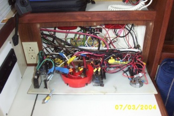
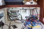
Our boat, a 1988, hull #563, came with a fully-developed "rat’s nest" behind the stock Seaward panel. AC and DC systems were not isolated from one another, and 16 years of neglect had taken their toll—including some fittings that had corroded through completely. One AC common fitting failed and grounded against a nearby DC ground. Fortunately, I was on the boat when this occurred and was able to power down and trouble shoot. The damage was confined to end of the AC wire that failed. If we weren’t onboard, however, there could have been a fire. This was sufficient motivation to clean up the entire electrical control system, including new panel components.
Working safely
The safest way to work on your system is to power it down completely. Ensure that the shore power cord is completely removed so a Good Samaritan doesn’t plug it back in for you! If you have an inverter, ensure that it is completely de-powered, i.e., DC power leads must be removed. Many inverters go into a "sleep" mode if there are no AC draws on the system—this is not a safe mode! Even a 12-volt DC power system can develop amperages sufficient to injure or kill. If you’re the least bit unsure of how to proceed, ensure that you consult with a qualified marine electrician. Time spent studying a reliable text is time well spent before starting a project like this. Ensure that you discipline yourself to always power-down when you are working around a potential shock hazard. The temptation will always be high to avoid climbing up to the cockpit or over to the dock to disconnect wiring as your project progresses. Another safety aspect is to provide a power supply to your bilge pump. In all likelihood, it’s hotwired to the battery and should remain so throughout the project, except when you’re aboard working (you’ll need to remember to reconnect it at the end of every work session).
Checking for available space
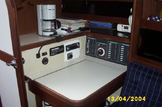
Perhaps the most important consideration is the space available for a new electrical control panel. The obvious solution is to obtain a "drop in" replacement from either Catalina or Seaward Products. This should fit in the hole that your current panel occupies. However, the panels have changed over the years, and each hole is simply hand cut at the factory with a saber saw, so some trimming may be required. If you build your own panel, use standard components (e.g., Blue Sea Systems) or obtain a custom panel, you may have to enlarge the existing hole. If it’s necessary to enlarge the hole, this process is greatly simplified if you remove the nav desk. The nav desk is held in place with screws and several through bolts. The screws can be accessed from the inside of the nav desk. The nuts for the bolts can be accessed through the wet locker and behind the old electrical panel. If you chose to remove the nav table as the first step in your project, remember to disconnect the shore power and the negative battery terminal. This will eliminate any chance of shock or short when removing nuts in the junction box.
In our boat, the panel was mounted on a thin sheet of teak veneered plywood that is fit against the fiberglass liner. This veneer piece was simply cut to fit and not attached to the underlying fiberglass except with the six screws that held the Seaward Products electrical control panel in place. After removing the panel and the adjacent 110v AC outlet, the wood veneer simply popped out. Another small piece of teak molding was simply wedged in place.
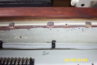
The hole is cut through the hull liner. This is approximately ¼ to ½" thick, and varies throughout, primary at joints where extra glass was added. If your cut out requires you to cut close to adjacent bulkheads, you’ll have to cut through thicker substrate. I used a combination of handsaws that mounted a saber saw blade and an old-fashioned hand jig saw that allowed for blade angle adjustment. A grinding bit that could be chucked in a drill also proved handy. The hole was finished with a combination of hand planning, filing and sanding with a small Black and Decker "Mouse" random orbital sander. Also note that the top of the factory cutout is nearly adjacent with the top of the liner (see Figure 7), in other words, it’s not practical to cut the hole any larger along the top edge. I had to grind relief spaces into this thick fiberglass to accommodate the nuts on the back of the reinforcing angle stock at the top of our new panel.
Another option would be to give up the shelf immediately above the electrical control panel. This would require removing the fiddle strip and cutting away a portion of the shelf/liner. This would allow the use of a larger electrical panel as well as providing additional area behind the panel for a larger breadboard. There may be enough room for mounting additional electronics as well.
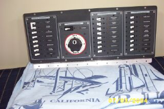
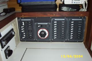
On our panel, we through bolted the aluminum angle stock for doublers along the top and bottom edge using number 8 screws that were countersunk into the starboard panel. The bottom doubler also serves as a convenient mounting surface for a piano hinge. When cutting out the hole for the panel, we had to relieve spaces for the nuts along the top edge (see Figure 7). This is a fairly thick laminate, so the easiest way to do this is to chuck up a cylindrical grinding bit in a drill. If you cut the hole large enough to accommodate the nuts, there isn’t sufficient backing to support the new panel. Another option would be to rivet the aluminum angle stock in place using flush rivets (flush on both sides—this would require the use of solid shank aircraft rivets). This would eliminate the need to relieve the underling laminate. Blue Sea components come with cutout templates. It is fairly straightforward to lay out these templates, and then mark the panel for cutting. A jig saw with a fine blade works well for cutting thin starboard. If desired, the edges can be finished with a file and/or sandpaper. Since our panel was only ¼ inch thick, we used machine screws and nuts to mount the Blue Sea components in place in lieu of the wood screws provided by Blue Sea for mounting.
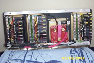
We had to finish populating each panel with circuit breakers, labels and backlighting kits prior to installing them in the main panel. This is much easier if you finish each individual sub panel before you mount them. Then, after mounting, connect the wiring for the backlighting as well as making appropriate sized jumpers. Remember to size the jumpers to carry 100% of the design circuit load. Our system uses 2 AWG wiring for the primary circuit.
Building a "breadboard"
After you’ve sorted out all of the wiring, and built or obtained a new electrical control panel, the next step is to build a breadboard behind the panel to simplify circuit lay-out and maintenance. This step is not absolutely necessary, since most quality electrical control panels will include all necessary breakers and busses, and theoretically, all wiring could terminate at the control panel board.
In our boat, the factory glued three small strips of 1" by 1" soft pine to inside of the hull. The small stock busses were screwed into these strips, as were the two red DC "backlights." For our new panel, we needed more space to mount busses, terminal strips and a small fuse panel (which serves as our electronics buss). Additionally, I wanted an easy mounting for strain relief for all of the wires and bundles running to the control panel.
The easiest way to organize everything is to mount a breadboard behind the panel. We used a piece of ¾" thick plastic starboard, but plywood would work just as well. Our board is 10" x 18". Keep in mind that plastic board can’t be glued, so if you choose to epoxy the board directly to the hull, you’ll have to use wood. We simply screwed the starboard to the existing strips. The screws were countersunk, so as not to interfere with the equipment and wiring mounted to the finished board. Also, although it should be obvious, use care when drilling into the area adjacent to the hull! You should never drill into the hull. The soft pine Catalina installed in our boat only required very shallow pilot holes with appropriately sized screws.
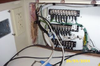
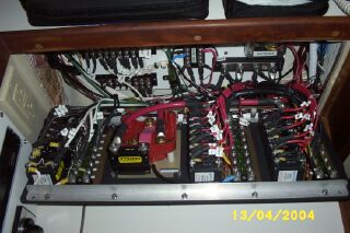
| To further permanently secure the board in place, I slathered some 3M fast cure 5200 on the mounting strips after all of the hardware was in place and circuits properly run. This allowed me to remove the board throughout the modification process for labeling, drilling etc. Figure 5 shows a picture of the AC side of the breadboard. Note the extent of the cut-out required in the liner. It literally uses all of the possible space available without removing the shelf. Also note the main GFI outlet has been relocated to forward of the nav table. The edge of the bottom cut is only about 1/8" above the top of the nav table. It would have been much easier to make the cutout with the nav table removed. If you look at Figures 6 and 7, you’ll see that the top edge of the cutout is flush with substrate that makes up the liner. The liner and shelf are a fairly substantial lay-up, about an inch thick. The semi-circle cutouts are relief areas to accommodate the mounting bolts on the back of the panel doubler. The top fiddle remained in place throughout the project.
It’s actually easier to "build" the breadboard in the shop. After you check it for fit and drill the mounting holes, it can be removed and returned to the bench. This will allow you to fit various size busses, terminal strips and fuse panels to find a configuration that works well, is organized and fits in the space available. The toughest part of this job is working in the small amount of space available. It is possible to populate the board with equipment while it’s installed, but if you’re designing a system from scratch it’s easier on the bench. Another advantage of building "on the bench" allows you to easily write on the board, which is a very handy way to label circuits. |
If you do assemble your system in the boat, you may consider buying numerous components so you’ll have several options on hand—you can return the unused items after the fact. But you’ll save a great deal of transportation time by having numerous components on hand.
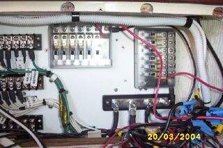
In our project we ended up using 2 ten-position terminal strips (with jumpers to convert them into busses) and 1 eight-position terminal strip on the AC side of the board. Using terminal strips with jumpers allows you the flexibility to configure them as required verses using bus strips. When space is a factor, this is definitely the way to go. On the DC side, we used a fuse panel for electronics and accessory items and a small sub-buss for cabin lighting. On both sides (AC and DC), there is sufficient space to add additional circuits in the future.
Wiring
The bottom AC buss serves as a "hot" buss for multiple appliances controlled by a single switch on the master AC panel. The left portion of the buss provides power to the two battery chargers and the right portion provides a common "hot" buss for all of the AC outlets.
In most cases, there was sufficient wire available to build the new bundles, but in a couple of cases, it was necessary to splice an extension on to the pigtails. Permanent labels were attached to all wires and a new schematic was drawn during assembly. Wires were trimmed to allow easy bundling prior to installing the end connectors. All connecters were crimped and shrink-wrapped. All AC components are sized to handle at least 30 amps. Appropriately sized circuit breakers protect individual circuits, and outlets are rated for circuit size. Outlet rating is only important for our air conditioning circuit, which is a 20-amp circuit. All outlets are heavy duty. Although we replaced all of the outlets on board, the original AC system was not in bad shape despite 16 years in a saltwater environment. This is a testament to the use of tinned wire and properly crimped and sealed connections.
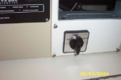
| One thing that’s a bit different about our AC system is the SeaPower unit we have installed. This is a 5KW engine-driven alternator system that is mounted at the base of the engine and capable of producing AC power when the engine is running. It takes about 3 horsepower to produce each kilowatt of electricity, so this unit can severely strain the 23 horsepower M-25XPA we have in our boat. These units are not recommended for small engines, but it was installed in the boat (and still worked!) when we bought it; so we’ve continued to maintain it. This second source of AC power requires use of an AC source or "isolation" switch. The function of this switch is to ensure that two sources of AC power are not simultaneously connected to the AC system. This type of switch is also required for generator and some inverter installations. This switch is mounted forward of the nav table and accessed via the wet locker. The white starboard panel covers the hole that the pre-historic LORAN was mounted in and also has the mounting bracket for the stereo control head/CD player. |
|
DC Systems
The DC system was a more complicated modification than the AC side. Our boat still had much of the original wiring installed, and had no battery monitor or fusing installed. So the project started at the battery box. We added a 150 amp main fuse to the positive DC wire as well as replacing all factory installed wiring (4 AWG) with new, tinned 2 AWG wire. Our house bank consists of four Trojan T-105 6 volt golf cart batteries for a total of 440 amp hours of capacity. These four batteries fit in the battery box, and there is sufficient room for the fuse, a shunt on the negative side for a Link 10 battery monitor and a 150 amp-rated ground buss. The only systems connected directly to the battery are the bilge pumps, battery chargers and Link 10 battery monitor. In-line fusing is used immediately adjacent to the mounting posts. All cables and fuses are labeled and spare fuses are stored adjacent.
| The DC side of the breadboard consists of 20 fuse panels, a heavy-duty DC ground buss and small lighting sub-buss. The use of the fuse panels eliminates all in-line fusing. And if a piece of equipment has an internal fuse, the fuse at the panel is one size smaller to simplify troubleshooting. One fuse panel is used to power "accessory" equipment (fans, stereo, etc.) and the other "electronics" (speed, depth, GPS, etc.). A separate circuit is provided for the autopilot. Each fuse panel supports six sub circuits, which allow for adding equipment in the future. If you design a system using this technique, keep in mind that the main breaker must be sized to support the nominal maximum load when all six circuits are hot. For most equipment the draw is small, but if you are powering anything that requires 20-30 amps (e.g., a stereo amplifier), you’ll need to ensure that the primary switch/CB is sufficiently sized to avoid tripping if everything were to be turned on at once.
The factory installed DC harness was easily adapted to the new panel, and the old wires were of sufficient length that they could be cut back far enough to remove most corrosion and accept new connectors prior to bundling and attachment. All DC wiring that ran through the bilge area (primarily bilge pump wiring) that was not tinned required replacement due to corrosion. The Blue Sea panels we used to build our system included ground busses, and we utilized those in our installation. An alternative would be to attach a large (e.g., 20 terminal) buss to the breadboard for grounding all circuits. We chose not to do this simply because the breadboard was populated, and there wasn’t sufficient room. If you do chose to use a common ground in this manner, ensure that it’s capable of bearing the entire load. For example, our system is sized for 150 total amps. The individual Blue Sea panels sized for 100 amps. There is a 100 amp main DC breaker as well as 150 amp battery fuse. Because of the main breaker, this is adequate as the 150 amp fuse need only protect the positive lead from the battery to the selector switch (i.e., it’s only serving as a backup). If the 100 amp breaker were not installed, then it would be appropriate to size the battery fuse for the system rating—in this case, 100 amps since the fuse now becomes the primary system protection. |
|
You’ll note if you study Figure 11 that the only color-coding used in our factory harness was red for hot, black for ground. The mast harness uses all red wiring, with color-coded stripes (the color coding of the stripes conformed to the electrical schematic—this was the only portion of our system beside the cabin lights that did). Aside from the blue wiring of the cabin lights, the only portion of the harness that matched the factory schematic was the mast harness. Fortunately, when removing the old panel, it was easy to label all of the wires as they were removed from their switches.
Battery Box Modifications
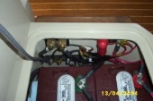
| Our boat had a smaller rat’s nest in the battery box. There was no fuse protection, and our new system has a Link 10 battery monitor. These two factors caused us to modify the equipment in the battery box to accommodate the Link 10, and add fuse protection for the main DC positive line. Since the Link 10 requires the use of a shunt in the negative line, we also chose to add another buss on the "output" side of the shunt to simplify wiring. Figure 14 is a top view of the 4 house batteries, and Figure 15 shows the fuse, shunt and DC buss. All primary wiring is new. We had just enough room in the sub-sole conduits to fit the larger gauge wiring. The large gray cable hanging to the left in Figure 15 is the wiring harness for the Link 10 monitor, which wasn’t hooked up when these pictures were taken, nor are the battery hold-downs installed. |
|
Installing the Main Panel
Our new panel uses a piano hinge installed along the bottom edge to allow easy access to the back of the panel. This required the addition of a teak strip inside the junction box. There’s a good view of this strip in Figure 10. Note that the liner is only about ¼" thick at this point. If you fit a similar strip, it will be necessary to trim the edge prior to gluing it with epoxy, since the inside of the liner is not a straight edge. If your nav table is removed when you install a new panel, you’ll have a good surface for clamping this strip in place. If not, there is only a small edge for clamping. I used spring clamps with the plastic tips removed to improve the grip along the available edge.
This project would have been simplified if a smaller panel were installed. The easiest change would be to remove the 1/2/Both panel and move it to an alternate location. Another option would be to consolidate some of the DC circuits to eliminate the need for a second panel.
Although the panel and breadboard look complicated, they are not. It’s just a matter of working one circuit at a time. No specialized tools beyond a good crimper, heat gun and wire stripper are required. The hardest part of the project turned out to be cutting the hole! Now we’re familiar with every wire on the boat and 100% confidence both the AC and DC electrical systems.
