Difference between revisions of "Engine Power Loss Diagnosis and Solution"
(New page: '''By Ron Hill, ''APACHE'' #788''' I was faced with a perplexing problem. The engine started, ran perfectly smooth from idle to high RPM, but lacked power when put in gear. I had lost ov...) |
Mark Elkin (talk | contribs) |
||
| (One intermediate revision by one other user not shown) | |||
| Line 1: | Line 1: | ||
| − | '''By Ron Hill, '' | + | ==The Injection Pump== |
| + | |||
| + | '''By Ron Hill, ''[[Apache]]'' #788''' | ||
Latest revision as of 07:34, 19 October 2011
The Injection Pump
By Ron Hill, Apache #788
I was faced with a perplexing problem. The engine started, ran perfectly smooth from idle to high RPM, but lacked power when put in gear. I had lost over 1 knot boat speed and about 600 RPM when the transmission was engaged.
When the engine was in gear at full throttle I noted there was NO black smoke coming out of the exhaust. After a couple of weeks of "head scratching," I determined that the engine wasn’t getting enough fuel. So, I started at the tank and ran a complete check of the entire fuel system: from the tip of the fuel pick up tube in the tank, fuel hose, Racor filter, electric fuel pump to the injection pump. I even changed out the injectors, but the engine still lacked power. I talked to a number of diesel mechanics and a Kubota dealer. They all stated that the injection pump was nearly "bullet proof" and should last the life of the engine. So I went over the entire fuel system again and the only item that I couldn’t inspect was the fuel injection pump. I decided to remove the pump and have it checked.
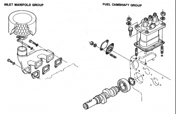
First I researched my M25XP Universal Service Manual (NO 1-89). It had some pictures and words that I found to be of no help. On the "Adjusting Fuel Timing" page of the Owners Manual (printed 8/87) it discussed removing the injection pump, but skipped a few steps (that I found out later). In the Universal M25XP Repair Parts Manual (11-1) there was a great schematic that showed the injection pump and how it fit onto the engine block (shown above).
To get to the pump you first must remove the air breather filter, the #1 cylinder glow plug (forward plug), and the three-injection fuel pipes from the injectors. Then clamp off and remove the main fuel line and the bleed valve fuel line from the injection pump. This allows you to get at the 3 bolts holding the inlet manifold in place. With the inlet manifold removed you can finally access the two nuts and two bolts that hold the injection pump in place.
The Owner Manual instructions state to remove the injection pump side cover so you can "visually check to insure that fuel rack pin (inside the pump) properly aligns with the opening in the top of the pump housing." I did this, but recommend skipping this step UNLESS the pump will not lift straight up easily from the engine block. That side cover is hard to get to and harder to reseal. Besides it’s difficult to see anything (the port is too low) until you slightly lift the pump up from the block. By setting the throttle at full speed, the fuel rack pin (inside the pump) should be all the way forward so it will clear through the small cut out notch in the engine block (see diagram).
With the fuel tubes attached to the pump, I gently rocked the pump back and forth while lifting up. The pump came straight off with no problem leaving the timing shims attached to the engine block. DO NOT TOUCH THOSE SHIMS! Cleanliness is paramount!! Your biggest problem is dealing with those bronze and blue chips from that damn engine paint that will come off when using wrenches and sockets (BTW - metric)!
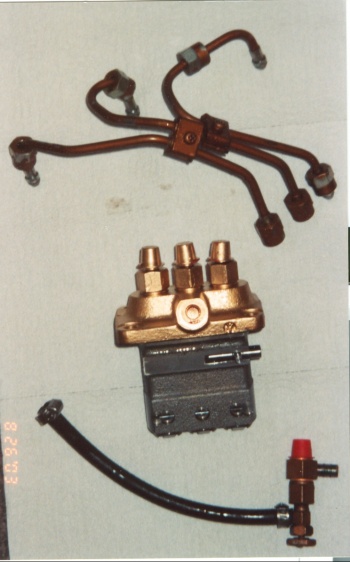
I took the injection pump to the same diesel shop that rebuilt my other injectors. The pump is a "KIKI" brand PFR type injection pump with roller tappets. All of the nice shiny metal parts in the inside of my pump were crazed and lightly pitted. The shop said they have never seen anything like it before and that the fuel contamination must have had a corrosive quality that destroyed the surface of that hardened metal. Hence the pump would not pump the amount of fuel necessary to attain full power. Who knows where I got that fuel from, but I immediately disposed of what was remaining in the tank.
Some important side notes. After you remove the pump, you will note on the port side of the pump is a data plate. Don’t screw around with that plate trying to clean it, as the numbers on the plate give the pump serial number, model number and order number (which are the internal parts and calibration data). Also on the starboard side of the engine block where the injection pump sat was imprinted D950 604294. This is the Kubota engine model (D950) and the block serial number. It’s too bad that serial number is in that location as you can hardly see it with the pump in place! That serial # is important to know. Sometimes parts guys want to know that number, as there may have been a parts change before or after that serial number.
I had to make a tough choice between buying a new pump or to rebuild the old pump. Each option would cost about $500, with the new pump being slightly higher cost. Usually that would be a "no brainier." However, after studying how a diesel injection pump is timed, I elected to go for the rebuild and use the same pump body (that was timed at the factory) with those same shims. I determined that I wasn’t capable of timing a diesel engine and neither were the vast majority of diesel "mechanics." I also could not be convinced that the machining of the new pump housing would be of such an exact same tolerance that it would duplicate the old pump housing so that I could use the same shims without retiming the engine. It wasn’t a hard decision for me to make, but nearly impossible to explain to anyone that doesn’t understand diesel timing. So you’ll have to do your own homework if you wind up in my situation, and make your own decision.
As I reported back to the diesel shop (that did the rebuild), that I only ran into one installation problem. They had repainted the pump housing on the top so it was nice and shiny. They had inserted plastic caps in the 4 threaded fuel portholes to protect the ports from spray paint. These caps should have been greased on the outside. I could have easily just wiped the paint off the top of the grease with a rag, and insured that no paint could contaminate the inside of the pump. Instead, I had to hold the pump upside down because the paint on those ungreased plastic caps flaked and chipped as I tried to remove them. Otherwise the reinstallation of the pump was straightforward.
I was somewhat disappointed at the information in the Universal Service Manual. However, between the Owner’s Manual information and the Universal Parts Manual pictorial blowups, I did the removal and reinstallation in about 5 to 6 hours (by myself) with little difficulty. Also, I was able to reuse all of the same gaskets.
Thankfully, my power problem was solved!

