Menu

Show posts

This section allows you to view all posts made by this member. Note that you can only see posts made in areas you currently have access to.

Show posts Menu

Messages - KWKloeber

#1
Tom

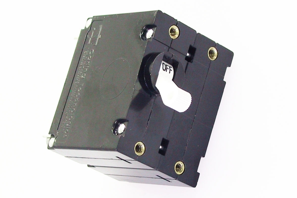
Here's a reason why it's key for owners to post pics when they have a problem -- the breaker on your panel is not like the one that I linked to and is not a safe breaker

It should be 2-pole, not single-pole, and therefore should be replaced with one of the type CD shows, or a double-handle-toggled breaker.

You didn't answer which white/black wires on the AC Terminal strip in your first picture are from the Smart Plug.  So does the shore power feed run thru the 30-amp breaker or does it go to the term strip?

The reason as others say that a breaker was later added at the transom is that ABYC requires the Main Breaker to be within 10 feet of the boatside inlet.

Without parsing what work you explained that you did to find the ground fault, generally:
  • Start with all connected (I presume that with the breaker off, there is no ground fault trip?)
  • Systematically start disconnecting circuits to isolate which one is causing the trip.
  • Then systematically isolate to locate what item ON THE tripped circuit is causing the trip.

It could be a failed GFIC receptacle.  That is common.   So start there and disconnect the circuit for the port/starboard receptacles.
Or the water heater possibly leaking current, so try that circuit next. 
Then the charger circuit. 

As you work thru it, reconnect whatever you disconnected before progressing to the next circuit.

 
#2
Quote from: Craig IllmanCTY didn't install a separate breaker (from the panel) closer to the shore power receptacle as specified in current ABYC standards.

Quote from: Ron Hillguys : It was in the 1988 production that the factory started to install a single throw, double pole 30 amp breaker with a reverse polarity light!!\

Craig/Ron,

Am I mistaken that this is an early Mk-I vintage panel like **should** be on Tom's 87? 


Isn't (like my 1984 C30 panel) the "AC Master" a 2-pole, single-throw, 30-amp breaker?

Tom,
The shore power hot and neutral supply should feed to it first in line. THEN, jumper over to the HOT and NEUTRAL halves of the AC terminal strip.

Here is the replacement (it can be found for le$$$ elsewhere):
https://www.catalinadirect.com/shop-by-boat/catalina-38/electrical/breakers-switches/circuit-breaker-double-pole-30-amp-ac-master/


I have actually Mod'ed my panel and replaced it with a Blue Sea double-handle, toggled main breaker (which fits in the same space on mine but had to move the Service and RP lights location.)
#3
@ Everyone

On EVERY Universal engine. EVERY ONE. The pump (facing it) turns CLOCKWISE, so it is easy to tell which hose barb the impeller SUCKS from (raw seawater from the thruhull) and which hose barb the impeller PUSHES through (to the Hx.)


**I have climbed the stupid tree and I own one in the backyard**!!

EDIT:
Quote from: KeelsonGraham on Yesterday at 12:51:16 PMI've also confused myself by thinking erroneously that the raw water pump takes water from the HX.
Also, many believe that the freshwater coolant pump "pumps" from the engine, TO the hose on the front of the gear cover. 
It DOES the reverse,  the coolant pump SUCKS from the hose on the gear cover and pumps coolant TO the engine block and TO the Water Heater (via the hose barb on the of the freshwater coolant pump.)

 
#4
@Keel

You circled the seawater SUPPLY elbow (a 1/2" NPT elbow/inlet to the PUMP) and its hose barb is 5/8" ID HOSE.

If you follow the hose (easily done) you'll see that it DOES NOT go to the Hx - it comes from the 5/8" barb on the seawater thruhull (or strainer.) 

The hose from the TOP hose elbow (which is also 1/2" NPT but 7/8" ID HOSE) goes to the Hx.

I previously posted resources on this forum showing the "B engine" hose routing and it is on the wiki:
https://c34.org/wiki/index.php?title=Flow_directions_in_engine_cooling_hoses_(both_early_and_B-series_engines)

Cheers
Ken


#5
Main Message Board / Re: Keel Bedding Survey
May 15, 2024, 10:49:23 PM
Quote from: High Current on May 14, 2024, 08:26:16 PMMy main reason to re-bed NOW would be to preserve integrity of the bolts.  BUT if I weren't going through this process I probably wouldn't be worrying about it...
Correction,
The Main reason ..... IF I EVEN NEED to rebed is...
I don't understand the foregone conclusion that you need to rebed (i.e., the bolts are compromised)?


QuoteDoes it crush the solid glass or only the wood core that I don't have?

at 105 ft-lb = ~10,000 lbf
 ≈ 25 MPa of stress.
But the entire section isn't compressed, just the topmost (floated?) layer of resin gets compromised.
 
https://www.boatdesign.net/attachments/fiberglass-strength-tests-pdf.148849/
Shows that the compressive strength of cured fiberglass resin is 55-mPa.

For a nominal 3/4" ID washer the stress @ 10,000#f would be ~30-mPa (if the nut doesn't bend the fender washer.)  Close enough to be possible considering that, naturally, strength depends on resin/hardener quality/characteristics and the quality of application.
#6
Main Message Board / Re: ? Sudden overheating?
May 15, 2024, 08:32:06 PM
Craig

The more I remotely wrap my feeble brain think about this, the more it leans toward the gauge. 

The Teleflex troubleshooting is checking only two extreme circumstances and nothing in between, like a "norm" midpoint.
It **could** be that the gauge pins high at anything above infinite resistance (when the S terminal is disconnected.)
Or it could read significantly high when the S resistance "says normal."


I couldn't see the forest -- (unless you have access to some resistors in the 50-ohm range to completely bypass the sender,) remove the sender and hook it up to the S and G terminals right at the gauge. 
If she still pins high (and the sender has a reasonable resistance value for the ambient temp,) your gauge is likely kaput. ***

***I say "likely" because it's a boat and we know that there are never any absolutes!
#7
Main Message Board / Re: ? Sudden overheating?
May 15, 2024, 08:00:33 PM
Quote from: Schulcb on January 14, 2024, 10:13:57 AMAm I correct that if the sender isn't grounding to the engine (teflon tape), I would get a high temp reading?
The gauge **should** pin low if the sender is not grounded to the engine block (or read low if the ground has high resistance.)
When the gauge S terminal is grounded it **should** pin high.


Quote from: Schulcb on May 15, 2024, 03:15:23 PMIf the ground to the instrument panel is the culprit, wouldn't all of the gauges be giving incorrect readings?
The voltmeter could read OK because there is very low current to the panel gauges, so virtually no voltage loss.

The Tach "reads" the pulses from the alternator (the frequency of the AC output, not the amplitude.)  A voltage above about 7v will drive the tach, so it may read ok.

(I have no clue how your fuel gauge is wired) but it was common for CTY to run a separate ground from the fuel gauge direct to the tank bonding screw, so that may read OK.  You should be able to see if it has a separate ground.

Try checking the panel ground wire - for resistance to the engine block (is that where the ground is  established for the panel?)  You'd need to run a temporary wire back up to the panel to use as reference (or use the old temp sender wire if it is still there.)  HOWEVER, I'm not sure how the panel ground will affect the gauge reading. but I would not **think** it would make the gauge pin high.  That's something I have not run across before.

I find this good for troubleshooting
https://www.harborfreight.com/30-ft-retractable-test-leads-58024.html
I just wish that it was 16 gauge rather than 18.


I presume that your Temp alarm works?  Grounding the engine temp switch S wire to the block **should** sound the alarm.

This keeps pointing to a short to ground in the S wire but there is resistance there.   Maybe an intermittently bad gauge, but that is a huge coincidence that it goes intermittently bad between removing and reconnecting the S wire.

Does she have the Westerbeke black plugs on the harness (at the rear of the engine?)

This is real headscratcher since you already replaced the S wire.
#8
EDIT
What is the brown conductor for on the terminal strip? 
Brown is not a color that should be used on her  AC system.

For background what issue are you having with the shore power system?


Ok technically speaking, that is a terminal strip (do not always believe what an Owner's Manual says or CTY's terminology.)

Which black/white wires are from the SmartPlug?

It would be helpful if you post a pic of the front and back of your distribution panel.
#9
The shore power should not run straight to the bus powering the circuits.

Ok, I'm not educated on what a PO did or your particular panel (post a pic?) but, generally, the shore power cable runs to the panel main breaker, which feeds the bus that feeds the various breakers/circuits/equipment (like water heater.) 

That's "generally" - on my '84 panel for instance there's no bus; the 30a Main feeds to the Pos and Neutral terminal strips and individual fuses are wired to the Pos terminal strip. 
#10
Main Message Board / Re: ? Sudden overheating?
May 15, 2024, 01:07:26 PM
Quote from: Ron Hill on May 14, 2024, 02:51:53 PMGuys : Before you start tearing things apart - spend a few $$ on a heat detection gun and see what the temperature of the engine really is!!   :shock:

A thought

Ron

Perhaps you can post a link to your info about the engine cover grounding out the Temp switch.  I could not locate it.  Given what was explained so far that's the only explanation I see that makes any sense.
#11
Main Message Board / Re: Oil/temp warning
May 14, 2024, 11:20:07 AM
Edit - I've said it previously in this thread but will again. Tie down the wires so that harness movement doesn't get transmitted to the oil pressure switch terminals.  They fail too many times on the B engines. Wb doesn't put a spring-coil of wire on the sender wires to absorb vibration/movement. 
***

David where exactly where the two ends disconnected?  Were they quick-disconnect terminals?

Does she still have the black rectangular Westerbeke plugs on the harness near the back of the engine?

When did the fuel gauge stop working?

I would be rethining my choice of a mechanic if one claimed that I didn't need a harness ground wire connected!
#12
Main Message Board / Re: ? Sudden overheating?
May 14, 2024, 11:14:51 AM
EDITED

Craig this makes no sense to me. Pinning high is due to zero resistance at the gauge S terminal and you have 970 ohms there.  The R measured on the S wire should be very close to the R of the sender (depending on what gauge S wire you ran.)  However, you are measuring the two Rs by referencing two different grounds (directly to the engine block vs. the path back to the gauge G terminal, therefore, that could account for the difference***. (That might mean your ground up to the panel needs checking/ohm-ing/attention.)  ***Remember when you are measuring R using that method, you are measuring R of the entire circuit (i.e., from the panel, S wire to the sender, the sender, through the engine block to wherever the connection is for the ground wire going up to the panel, through the panel wiring, and to the gauge G terminal.  70 ohms difference corresponds to about 30 feet of 14 AWG stranded wire, so you are definitely in the ballpark given the theoretical resistance of the S wire and return circuit.

Still, the gauge should read a little lower (not pin high) if the R is higher at the gauge than at the sender.

You saw my questions about your engine cover?


Quote from: Schulcb on May 12, 2024, 08:03:34 AMAfter removing the S wire from the gauge, the resistance from the S wire to the panel ground (checked using the G post on the temp gauge) IS 970 ohms.  Checking the resistance at the sender again (cold this AM) is 900 ohms.

When the gauge started displaying inaccurate readings it was sporadic with it going from "pinned" high to reading normal.  Then the frequency diminished until it always reads >240.

This morning with the engine cool, when I engerize the panel the gauge reads ~170'F.

Not sure it this tells you anything...

Thanks,
Craig
#13
Main Message Board / Re: ? Sudden overheating?
May 11, 2024, 11:39:18 PM
When the gauge goes high, is the engine cover closed? 
Do you have foil insulation on it **(terminal shorting out)**
(see Ron's previous warning about that!!) 

If it is not already, insulate the temp sender terminal with a small BlueSea terminal cap.


Quote from: Schulcb on May 11, 2024, 05:45:19 PMI to G terminals is 12.5V. 
No wire on the "S" terminal, gauge rests below 120'F.
"S" and "G" terminals are connected, gauge reads >240'F.
It APPEARS that the gauge is OK


Quoteresistance of the sender is 435 ohms at 97'F.
That APPEARS reasonable for that temp.  That was with the S wire disconnected from the sender correct?


QuoteI ran a new wire directly from the sender to the "S" on the gauge.  Gauge still shows >240'F.

Based on #3 on the troubleshooting guide, is the sender shorted (0 ohms)?
What #3 refers to is:  "If you short out the terminal on the sender, the gauge will (**should**) read >240.
You measured the sender (said it was 435 ohms -- so no, the sender itself appears to not be shorted out.)


QuoteI don't think they are around any longer.
Along with nearly all other manufacturers (Guest, Ancor, etc, etc,) Teleflex gauges have been gobbled up by SeaStar Marine.  I doubt they can help much beyond what is in the troubleshooting steps.

Remove the S wire from the gauge.  Check the resistance from that wire to panel ground.
  It **should** read the same as the temp sender resistance

#14
Main Message Board / Re: Oil/temp warning
May 11, 2024, 10:57:59 PM
Quote from: dclintonbaker on May 11, 2024, 09:21:16 PMthanks for your continuing interest Ken.
Oil switch is an open circuit with the engine off and closed circuit with the engine running.

My current project is the reconnect all of the leads from the engine to the harness that runs aft to the instrument panel.

@d

Did your mechanic do any troubleshooting (before or after replacing the switch and alarm)?

Your switch is operating correctly.  (The closed switch when you have oil pressure is supposed to power the fuel pump.)

With the key switch on, check the voltage at both switch terminals to ground.

Then we are going to take the switch out of the equation so we can test with the engine off (no oil pressure):

  • Make up a short male-to-male jumper
    (or get a male-to-male adapter at the auto parts)


https://shop.advanceautoparts.com/p/dorman-disconnect-interior-adapter-assortment-85412/22141457-p

  • Jumper together the two terminals.


  • Tape it so it can't short out to the engine.


There should be TWO wires on one of the terminals, so check around to ensure there's nothing loose. 
Something appears to be abnormal on your harness because there **should** be a third wire (probably blue) running from the switch (your yellow terminal) to the alternator EXCITE terminal.

With the switch terminals jumpered and key on, listen for the fuel pump clicking.  
Does the alarm sound?  Faint or loud?


Report back!


The harness should have two wires on one terminal (red/white and ?blue?)
#15
Main Message Board / Re: Oil/temp warning
May 11, 2024, 12:10:50 AM
Quote from: dclintonbaker on May 10, 2024, 07:13:07 PMTesting the new oil pressure switch..engine stopped, open circuit  from both tabs to engine ground.
    "                    "          engine running, open circuit from both tabs to ground.

The switch is between the two terminals.
Not the terminals to ground. 
Recheck the switch.


Quoteno tachometer reading, no fuel gauge reading and the temperature gauge reads ~ 200 F after engine running for 1 minute.

I presume with the items still disconnected as you described below?