Tech Wiki

A step-by-step guide

By Mark Elkin, Yorkshire Rose #133


Yorkshire Rose, hull #133, was built by Catalina Yachts during their first full production year. At that time, CY didn't even plan for an anchor windlass. For all the years I've owned Rose, I've raised the anchor by hand and muscle. And wished for a windlass most of those times. I've eyeballed the Lewmar Anchorman, a low profile manual windlass for a while, but kept putting it off. Finally, the time came (i.e. I got married) to stop procrastinating.

During a boat show, I talked to the Lewmar representative and learned that they had an electric version of the Anchorman. They had discontinued this line but the local vendor still had one on his shelf. So out flew the credit card....

Now came the challenge: where to mount this thing. Fortunately, a couple years ago, Mike Smith did a similar installation. So, following in Mike's footsteps, I tackled this project. What follows is the nitty gritty details.

The windlass motor requires protection from the elements. Since there's no "box" in the anchor well on the early model C34 boats, my best option was to put the motor inside the V berth. That, of course, meant cutting and drilling into the deck above the V berth. And then creating a water tight seal between the flat surfaces of the windlass capstan and windlass motor and the curved surfaces of the deck and the cabin ceiling. YIKES!!!!

I started out with the idea that I'd get some 1/4" teak plank, cut it to the correct outline of the windlass parts, then meticulously sand one side of each to match the curvature of the deck or ceiling. Fortunately, about the time I was ready to start the sanding part of that job, I read in the Mainsheet about another owner who needed a flat level surface for mounting his new, extra starter battery. He described how he created this by pouring unthickened West Systems epoxy into a mold right on his hull's fiberglass. And the proverbial "light came on" in my head. This would work great for the top side, which is the part that truly needed the watertight seal.

After that, it was all just details. The pictures below show the details as the project progressed.

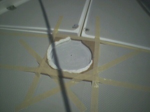
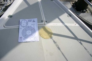
01-epoxy-mold-installation.jpg Day 1 at the boat. First I sanded down the deck where the capstan will be mounted to remove the gel coat and to rough up the surface. After drilling a pilot hole to mark the center, where the shaft hole will eventually be cut, the mold was taped down and then lined with modelling clay. The clay prevents the epoxy from permanently attaching the mold to the deck! The mold was made from a piece of Masonite. Easily started with a jigsaw and finished Xacto knife.
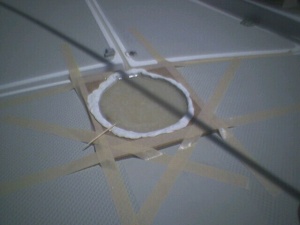
02-epoxy-mold-installation.jpg Mixed up the epoxy and poured it into the mold. A prior practice session at home taught me that no matter how carefully I mixed the epoxy and hardener, air bubbles would get trapped into the fluid. But the solution was simple, pop the bubbles (with the toothpick) before the fluid started to harden.
03-epoxy-pad.jpg After a couple hours, the epoxy hardened enough that the mold could be removed. I mixed another small batch of thickened epoxy and applied that around the edge to create the fillet before the pad cured too much. I did all this on a Sunday and let it finish curing during the week. The epoxy doesn't need that long to cure, but the next steps would require two days to do right and I wanted those to be consecutive to minimize my exposed "hole" time.
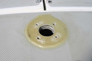
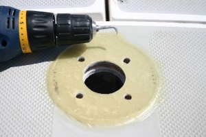
04-gouger.jpg Day 2 at the boat. Now came that really scary part. Holes, including a really big one, in the deck. I didn't know how thick the deck is at this location, nor how much is fiberglass shell and how much is wood core. It turned out to be 7/8 inch thick. From top to bottom: 1/8 inch fiberglass, 3/8 inch plywood, 3/8 inch fiberglass. My epoxy pad added another 1/8 to the top.

After drilling the holes, I had to gouge out the plywood exposed at the edge of each hole. Additional epoxy will replace the removed wood to both seal and strengthen the holes against the compression forces of the mounting bolts. Here's my gouging tool.

05-crap-catcher.jpg Of course, all the drilling and gouging creates a mighty mess. But a plastic garbage bag and some masking tape helped to contain a large part of it.
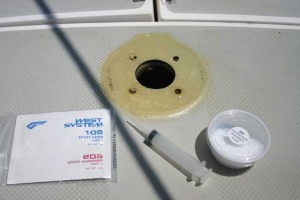
06-hole-reinforcement.jpg The materials and tools needed to fill and seal the holes. First I mixed a batch of thickened epoxy and sealed the big center hole. That was smeared into the gap where the plywood had been removed. I had to do the center hole first first because the plywood between the center and side holes had broken through in a couple places. After the center was sealed, then I mixed an unthickened batch and used a syringe to inject the fluid into the bolt holes.
07-unpainted-pad.jpg Day 3 at the boat. With the epoxy hardened, I simply had to redrill the mounting holes and then sand down the top surface to get that final smooth flat surface.
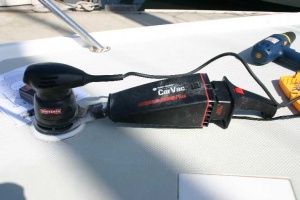
08-shop-vac-boat-version.jpg Sanding epoxy can be quite messy. And normal shop vacuums are not quite as handy around a boat as they seem to be in the garage. But a little ingenuity (and luck) is all it takes. My car vacuum's accessory attachment piece just happened to fit snugly into the sander's exhaust port and did a better job of pulling the dust away than the sander's catch bag would have done.
10-capstan-fit-check.jpg Now just test fit the capstan. Perfecto! The gods were shining down.
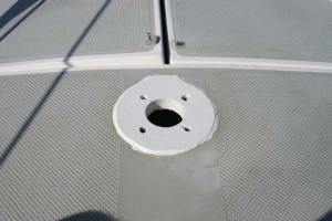
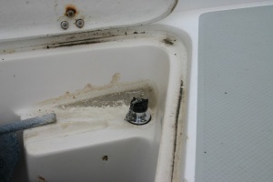
11-finished-pad.jpg A coating of topside hull paint makes it look almost professional, and adds a layer of weather and UV protection to the epoxy pad.
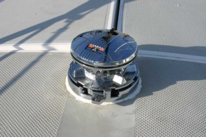
12-capstan.jpg Finally, apply a bead of 3M's 4200 around the holes and the outer ring of the pad. Slip the capstan into place.
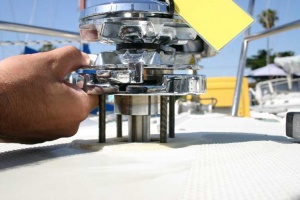
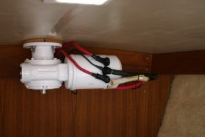
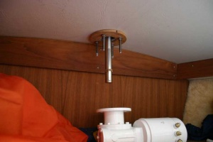
13-motor-and-shaft.jpg Inside the cabin, I kept my original idea of a shaped teak pad. It's kind of hard to duplicate what I did topside when gravity is fighting you all the way. Anyway, I just lightly finger tightened the nuts to the bolts while the 4200 cured and called it a day.
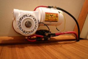
14-wired.jpg Day 4 at the boat. Time to mount the motor. But first try showed a major problem. The threaded-rod bolts are too long. The bottom out against the motor body itself before the top mounting surface got to the ceiling. Only two choices now: get shorter bolts or a much thicker wood pad. I chose the former. So with the capstan still in place, I removed and replaced each bolt with one that was correctly sized.

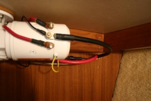
Day 4 and 5 at the boat. Now that the motor and power switching solenoid were in place, it was time to connect the 12V power. First I removed the forward trim panel to see where I could route the wire and controls. Turned out fortunately. There's a little gap between the anchor well side and the hull on the starboard side that has access to the bilge under the anchor well. This gap was actually created by a molded "hanger" for Danforth style anchor flukes. (Shown several pictures below) So I fished a lead line down and then pulled the power cables back up. After agonizing momentarily, I bit the bullet and drilled the slotted hole in the forward trim panel and fed the cables through.

15-solenoid.jpg The control solenoid is mounted to the forward cabin wall, behind the motor body.
16-controller-plug.jpg I made the hand controller from a marine weatherized rocker switch, a plastic "hobby box" from Radio Shack, three strands of marine 16 AWG wire, and a marine weatherized deck connector. The deck fitting piece neatly fit onto the Danforth hanger in the anchor well, and is only inches forward of the V-berth forward bulkhead wall.
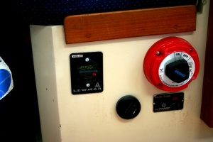
18-circuit-breaker.jpg Day 6 at the boat. The power cables are routed back to the battery box along the starboard hull. Under the V-berth I secured the cables with screw anchorable cable ties to the underside of the V-berth sole. The cables then pass through the hanging locker walls into the main cabin, under the starboard settee. Still following the starboard hull until they finally turn toward the battery box, crossing on top of the water tank. Inside the battery box, the ground is secured to the negative side busbar. The 12V cable leads to the circuit breaker, newly mounted in the battery box wall.
19-finished.jpg Day 7 at the boat. After the test run, the exposed power studs and covered by rubber caps and the wires are neatly dressed with cable ties.


I've only tested the anchor windlass in the harbor. But we're now ready for the next cruise.

Oh, one more thing. My mate thinks the motor is an eyesore. So that's prompted the next project.


Mark Elkin Yorkshire Rose #133