|
Windlass Inside Double Door Anchor Well
For over 19 years I’ve always wanted a windlass. However, the first production year of the C34 that had an anchor well specifically made for a windlass was 1989 – the year after APACHE was built! That molded in box in the right rear corner of the anchor well was made to hold a horizontal windlass. Catalina also went to a single anchor well door for that and subsequent C34 production years. I have never liked the windlass on the deck (and aft of the anchor well) with the motor extending down into the V-berth, as some C34 1986/87/88 owners had done. I wanted a clean deck. A search of the C30, C34 and C36 owner data found that no one had installed a windlass inside a double door anchor well, which is where I wanted mine mounted! I had always been meaning to come up with a design for that installation. I suddenly found that I was the owner of bilateral inguinal hernias and pulling the anchor/chain was no longer an option. My need for a suitable design rapidly moved to the top of my “to do” list!!
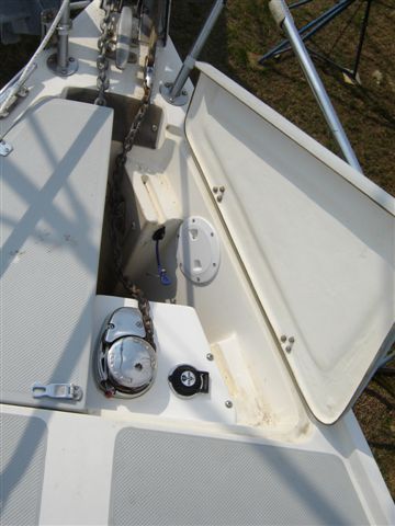
Windlass one door closed
The major unknowns were to first select a windlass and then figure out how to secure it inside the anchor well. The factory uses a horizontal windlass with the motor at 90 degrees. With an “open” anchor well I decided to use a vertical windlass. A vertical windlass has some nice advantages over a horizontal one. It was lighter in weight and can use a smaller motor because there is no 90 degree turning mechanism. A few other nice features were that the chain/rode was in the gypsy about 160 degrees rather than 90 degrees for a horizontal version. This alleviates the problem of the chain not fully engaging the “teeth” of the gypsy. Verticals also seemed to be a lower price, I’ll guess because they didn’t have that 90 degree turning mechanism. The main vertical disadvantage was that I couldn’t have both a drum and a gypsy because it would be mounted too low in the anchor well. I decided on a vertical with a gypsy that could handle both line and chain. I selected the new Lewmar V700 and a search of the internet found much better pricing than in any of the Marine chandleries! That internet pricing was also much cheaper for the marine grade wire, connectors, heat shrink and split loom wire covering.
After selecting the Lewmar V700 the big problem was what was behind that teak bulkhead at the head of the V-berth so I could figure out: 1. How to route the primary power wiring? 2. Where to mount/install the solenoid (control box)? 3. How to run the motor and the foot switch wires to the solenoid? 4. The least of my problems was where to install the circuit breaker and where to connect into the battery/s.
I had installed a second shelf above the factory shelf at the foot of the V-berth, so they both had to be removed. I decided to route the power wire along the starboard side of the boat, because I had a starting battery just forward of the starboard water tank. I then removed the underside Naugahyde covered plywood strip that runs the length of the starboard V-berth just under the cabin light. This strip hides the wiring from the bow for the starboard side cabin lights. Next to come off was the center teak facing strip on the top of the teak bulkhead above where the shelves used to be. Then I had to take off the cabin light by removing the screws and cutting the wires. Next was to remove the screws on the vertical starboard V-berth teak facing piece. This long strip of teak was a little difficult to get out because it was tightly fit into place. Now I could see from the upper corner, that the teak bulkhead was a piece of ½ inch teak veneer plywood that was perfectly cut to fit and touch all sides of the hull liner and the V-berth platform. I drilled out the 6 teak plugs and removed the screws that held the teak bulkhead in place. The teak bulkhead pulled right off. However, to my surprise I found that a piece of ¾ inch plywood with about a 1 inch gap on all sides had been caulked/glued to the cabin side of the anchor well! I still didn’t have a clear view/idea of what the cabin side of the anchor well really looked like. I suspected that the aft molded portion that was made to hold the Danforth type anchor was hollow, but I still couldn’t see that. After a few mighty pulls on that plywood it finally broke loose leaving some of one “ply” still glued to the cabin side of the anchor well. Finally I could see the entire cabin side of the anchor well and those Danforth indentations were in fact hollow on the inside.
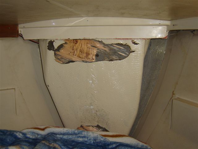
Windlass V-berth anchor well side
Now that I knew what the anchor well looked like from the inside I determined that the two pieces of plywood together (1 ¼ inches thick) would make an adequate “backing plate”. In between tearing up the V-berth I was designing a bracket to hold the windlass and where it would be placed/mounted inside the anchor well. I measured the height of the V700 from its mounting base to the top. That measurement was 2-5/8 inches. I made a flat cardboard cut out of that design and found that the top of the aft starboard Danforth mold could support one side of the windlass bracket, would also be horizontally deep enough to close the anchor well starboard door all the way and the windlass would align with the chain run from the bow roller. (I installed my bow anchor roller. The 1989 was the 1st production year for a factory installed bow roller). From that flat piece of cardboard I made a three dimensional cardboard/duct tape model adding a back and a gusset port side for extra support.
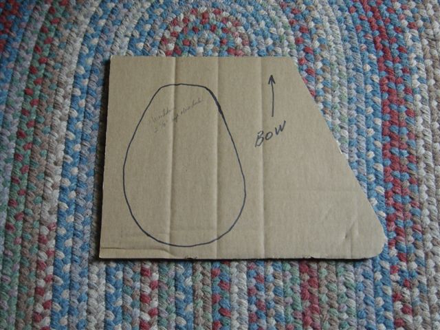
Windlass top cut out
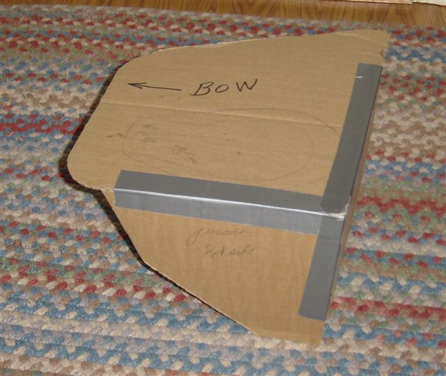
Windlass cut out 3D
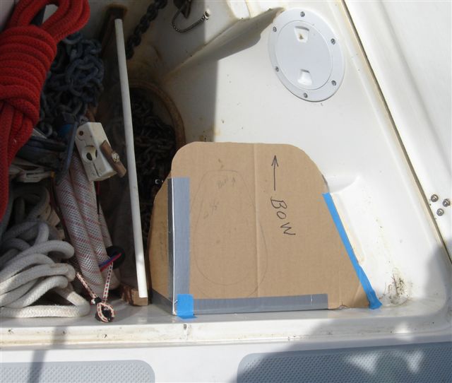
Windlass cutout installed
The next step was to mix up some West System (epoxy) and lay up alternating layers of mat and cloth over the waxed paper covered model, soaking down each layer with the epoxy until a 3/8 inch thickness was attained (10 layers). After the epoxy set overnight it was trimmed, sanded and sprayed with a gelcoat primer. I also rechecked to make sure that it was an exact replica of my cardboard model. Then I made the cutout hole so the windlass would fit in the bracket and drilled 4 mounting bracket holes in the back, making sure that the windlass motor would not block those holes! I was satisfied that my homemade bracket was strong enough to handle the torque of the windlass. The bracket is surprisingly heavy!

Windlass platform cardboard to fiberglass
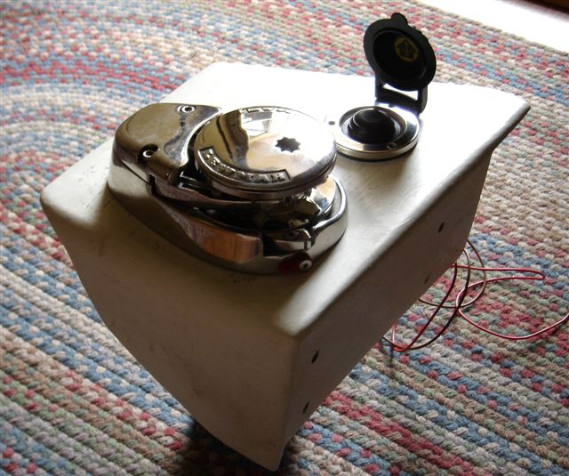
Windlass & footswitch in platform
Lewmar recommended #4 gauge wire for runs much longer than the 18 feet that I estimated I would need from the starting battery (just forward of the starboard water tank) to the anchor well. I initially thought that the wire would run from the starting battery, under the settee, and go up thru the front of the salon sliding compartment, into the cabin light wire run under the starboard salon deck. I found there was no space under the slider as the hull liner and hull became one! The only other route was thru the bottom of the hanging locker, up the hull inside the locker and come out thru the counter top in the far aft outboard corner of the top of the hanging locker. That worked and the wire then went up to join with and parallel the cabin light wire toward the anchor locker (the run was16 feet long) I use that corner to stack all of my engine and other equipment manuals, so they would cover the wire. After that wire route was decided upon, the placement of the circuit breaker under the forward starboard settee was obvious. The breaker was easy to install between the battery and the + wire going into the hanging locker.
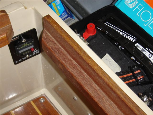
Windlass circuit breaker
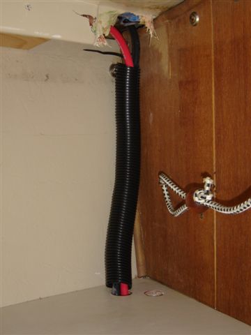
Windlass wires exiting hanging locker
Next was where to install the solenoid. It was a tough choice, but I decided to mount it on the starboard hull high just inside where the plywood bulkheads would be reinstalled. I had dabbled with the idea of running the wires from the foot switch and the windlass motor thru the bulkheads and then mounting the solenoid on the V-berth side of those bulkheads. I didn’t want to drill extra holes thru the teak bulkhead, so time will tell if I made a wise decision. [There is also another wire routing option of connecting into the battery selector switch for power, and running the wires inside the vertical port side teak that covers the holding tank vent. The breaker could be mounted in the panel or in that teak face cover and join the windlass wires with the running & cabin light wires all the way to the front of the V-berth. This routing can also be done for 1989 and later boats, that did not come with a windlass installed. I know of a 1989 and 1990 boat that have done this and mounted the Maxwell 800 in preference to the smaller 500.]
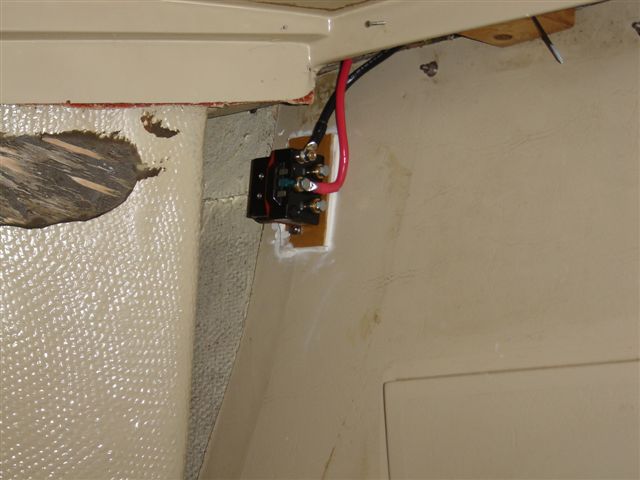
Windlass solenoid starboard side
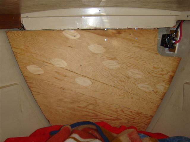
Windlass first plywood bulkhead
The solenoid was mounted on a 3/8 inch thick piece of plywood and caulked to the hull. I then remounted the ¾ inch plywood bulkhead using caulk and a few screws to hold it in place. Just previous to that mounting I had cut out a small upper starboard corner out of the plywood bulkhead. This would enable me to get at the solenoid and wire when the bulkhead was back in place. With that ¾ inch bulkhead back in place I could drill the mounting holes and mount the bracket with windlass and foot switch. Before the final mounting and securing of the four longitudinal 5/16 inch bolts (thru the anchor well & plywood bulkhead) and the two ¼ inch bolts (thru the Danforth mount), the entire mating surfaces (of the back of the bracket and anchor well wall) were coated with 3M 5200 fast cure sealant. I had also cut some small ½ inch plywood squares to simulate the ½ inch teak bulkhead so I could tighten the bolts in place while the sealant cured and also cut the bolts to the correct length.
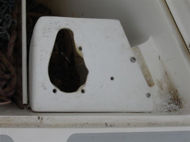
Windlass platform installed
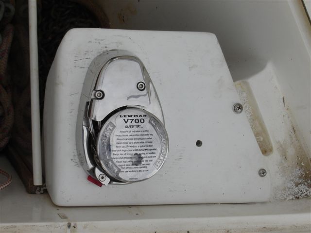
Windlass platform with windlass
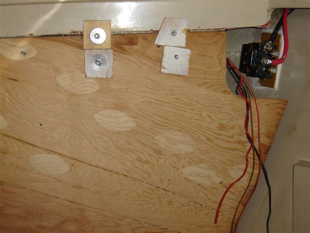
Windlass installed with wiring ready
To connect the wires I cut a ½ inch hole thru the starboard aft side of the anchor well and inserted a 2 inch piece of ½ inch hose. This hose was caulked in place and acted as a conduit for the motor and foot switch wires to go thru. The down angle of the hose was inside the anchor well to inhibit water from flowing inside. I did not cut/shorten any of those 4 wires, but got the correct length by making a wire bundle inside the anchor well and securing that bundle with wire ties. The wires were then connected to the solenoid and that conduit was filled with caulk on the inside and outside for waterproofing. After the sealant cured it was time for a test run. To my surprise I’d reversed the foot switch wires so I had a down rather than an up switch! That was corrected by simply moving the spade connectors on the solenoid!
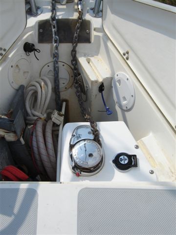
Windlass finished with both doors open
I crimped & soldered all connections and covered each connection with heat shrink. All paired wires were put in split loom wire covering and all ring & spade connections were sprayed with BO Shield for protection.
Now it was just a matter of putting everything back together. With the sealant cured, I pulled the 4 mounting bolts, reinstalled the teak bulk head, drilled holes thru that teak bulkhead and secured the 4 mounting bolts with self locking nuts on stainless fender washers. The old mounting holes in the teak bulkhead were filled with plugs and it was remounted using screws and finishing washers! Next was replacing the long teak strip on the starboard side and remounting of the cabin light. The center teak facing strip went back in place along with the starboard Naugahyde strip underneath the teak trim. I reinstalled the two V-berth shelves. I dabbed some flat brown (primer) paint on the stainless washers and nuts so they would blend in with the color of the teak bulkhead.
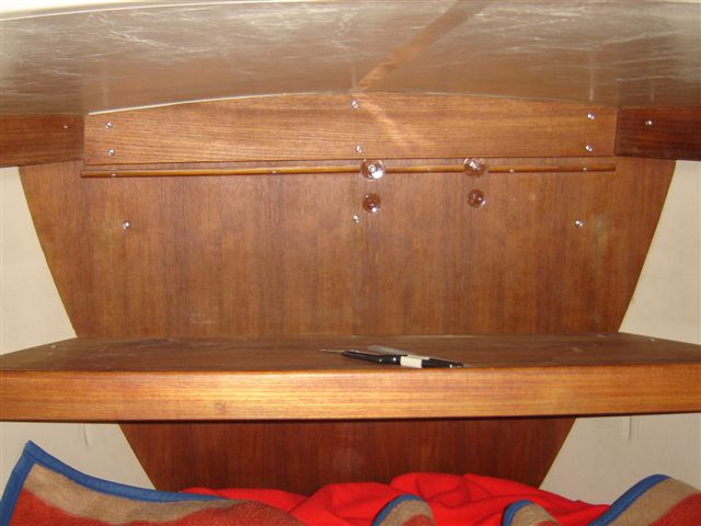
First Shelf
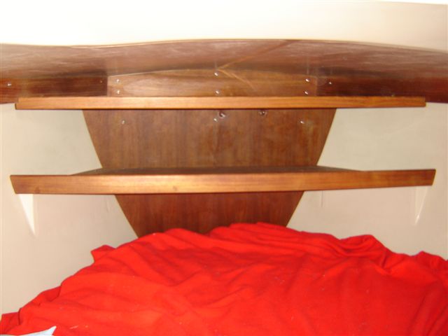
Second Shelf
Inside finished
As you could see from the pictures, I was staying on the boat while I was doing this installation, so the mattress was still on the V-berth (no place to put it!). The aft cabin was loaded with its normal stuff (cockpit cushions/throwable cushions/spinnaker/clothing from the forward hanging locker/etc/etc), so sleeping back there could only have been an option if everything were moved home! The cockpit was loaded with the dinette table, starboard salon cushions, seat boards along with the stripping I was removing and the 2 bulkheads. It’s lucky that I have a full winter cover as I underestimated how much of the boat I would have to take apart (all at once!) to do this installation! It sure was tough on your back having to scrunch down to work in the forward part of the V-berth!!
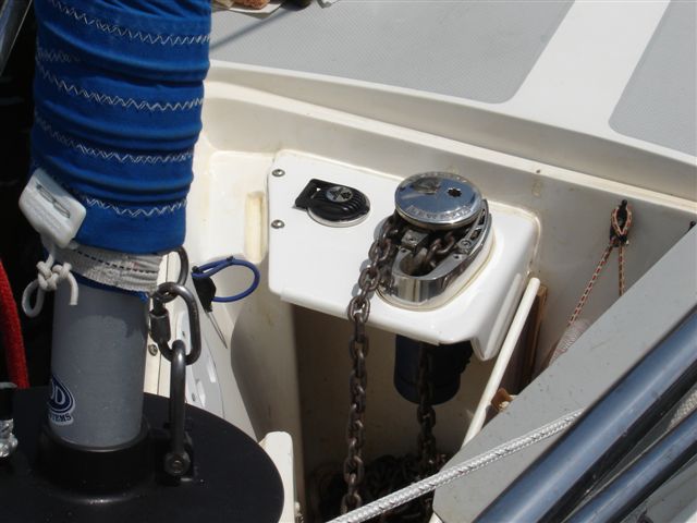
Windlass from bow
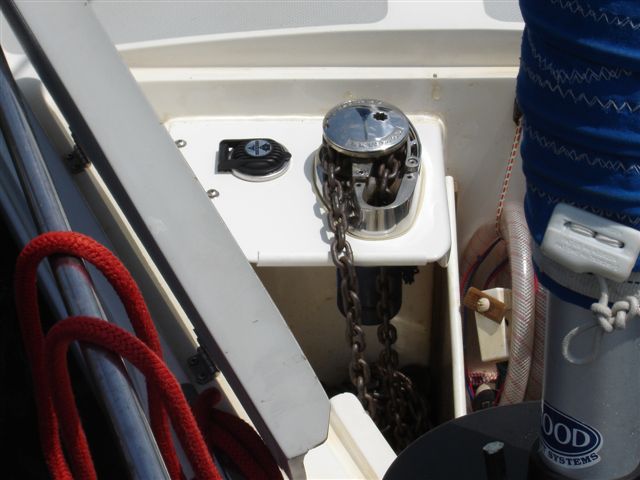
Windlass from bow
The Lewmar V700 I purchased had an installation kit (which included an up/down Toggle Switch and a Breaker/isolator). I had to replace the toggle switch as it was not made (or could not withstand) the corrosive wet environment of an anchor well. That meant I had to purchase an “UP” foot switch and a solenoid/control box. Even with those additional costs my installation was still under $900. I was also very lucky because when I made the bracket, the marina that I was at was doing an insurance job on a 1984 Catalina 30. A gelcoat side of the C30 had been chewed up in a storm. So when they “shot” that C30 with gelcoat, I had them spray my bracket. The match was perfect!!
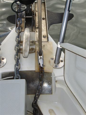
Lexan Chain Guard
After the complete installation was checked for proper operation; I decided to add a thin narrow piece of Lexan between the end of the bow roller and the start of the anchor well. This Lexan acts as a buffer (guard) so the moving chain cannot nick or chip that deck gelcoat.
Ron Hill
APACHE #788
